Stud welding attaches a metal fastener to a workpiece from one side. That makes it useful when the back of a panel is inaccessible or a through-hole would complicate sealing and assembly. The process can be fast, but the weld still depends on the stud, base material, surface, power source and procedure working together.
For a B2B buyer, the first decision is which process fits the part: drawn arc for many structural and heavy-section jobs, or capacitor discharge (CD) for many small studs on sheet metal. This guide covers the cycle, the parameters worth specifying and the questions to put to a supplier before ordering equipment or consumables.
Basics of Stud Welding
What defines this joining process?
In stud welding, current creates an arc between the stud end and the workpiece. Both surfaces melt locally, then the gun drives the stud into the molten pool. The joint forms as the metal solidifies. The process needs access to one side of the workpiece; it does not need a drilled hole or a nut on the reverse side.
A sound stud weld is not automatic. Joint strength depends on the stud material and geometry, the base metal, weld area, settings and inspection. Avoid using a catalog statement such as “stronger than the stud” as a substitute for a qualified procedure or test.
How does the welding cycle work?
- Position: the gun holds the stud square to a prepared surface and completes the electrical return path.
- Initiate: the operator triggers the programmed weld cycle.
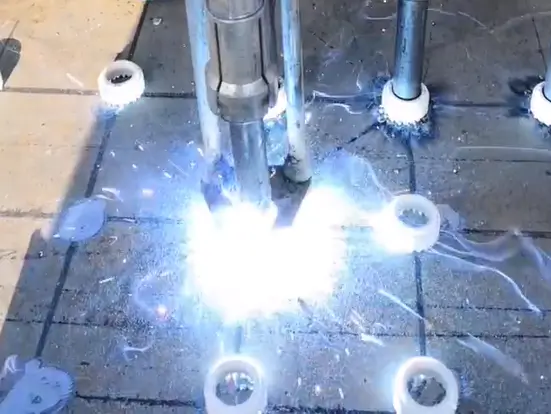
- Lift and arc: in a drawn arc cycle, the gun lifts the stud and current melts the opposing surfaces.
- Plunge: the gun returns the stud to the molten pool; the joint cools before the gun is removed.
Factory check: run trial welds with the production stud, base material, gun, cables and return-lead layout. Record the settings that pass the required inspection; do not copy a setting from another job without checking it.
| Cycle item | What to verify | Why it matters |
|---|---|---|
| Surface and fit-up | Clean weld area; stud seated correctly | Contamination and poor alignment change the weld |
| Programmed cycle | Current, time, lift and plunge as applicable | These govern arc behavior and molten metal |
| Acceptance | Visual and specified mechanical checks | Appearance alone cannot prove joint strength |
Stud Welding vs. Traditional Methods
When does it avoid drilling and tapping?
A welded stud can remove the drilling, deburring and tapping steps when the design permits a welded attachment. That can simplify assembly and avoid a through-hole. The comparison changes if the joint must be removable, the reverse face must remain cosmetically untouched, or the base metal cannot be welded with the proposed process.
Is it faster than manual fillet welding?
The weld cycle is short, but the production rate includes loading studs, moving the gun, preparing surfaces and inspecting welds. Automation may reduce handling time on repeated layouts. Ask a supplier to demonstrate the full cycle on your part and record accepted welds per hour, rather than quoting only the trigger-to-plunge time. Consistency also depends on controlling all critical variables, not just current and time.
| Joining method | Typical preparation | Check before choosing |
|---|---|---|
| Drilled or tapped fastener | Hole making and deburring | Access, sealing and serviceability |
| Manual fillet weld | Fit-up and weld access | Weld size, operator qualification and inspection |
| Stud welding | Surface preparation and matching stud | Material, thickness, equipment and test result |
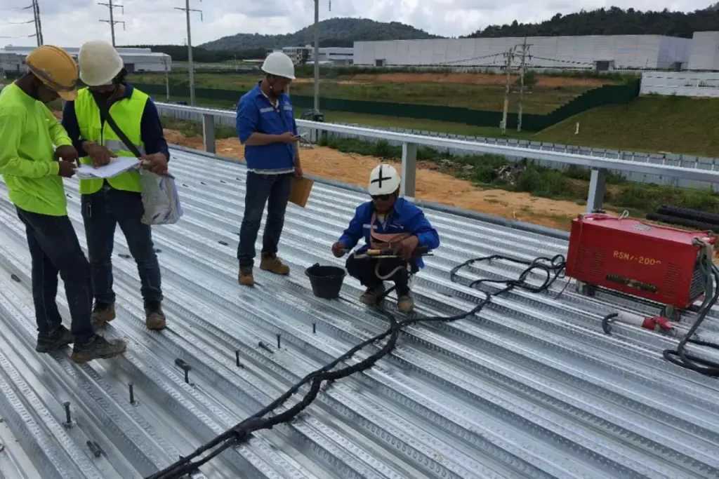
Equipment for Stud Welding
Selecting the right power source
Start with the process and stud size range, then check the machine’s rated output, duty cycle, input power and cooling requirements. Transformer units and Drawn Arc machines are different equipment choices; weight alone does not establish which will give an acceptable weld on your material. Compare their published ratings under the same production conditions.
A duty-cycle figure matters when a line makes repeated welds. Read the manufacturer’s rating and cooling instructions to prevent overheating. Also confirm cable lengths, site voltage and the return path before comparing quoted machine prices.
Choosing the correct gun and accessories
The stud welding gun must match the stud diameter, chuck, ferrule holder and power source. On a drawn arc gun, check lift and plunge adjustment and whether the foot assembly keeps the stud square. A damper or adjustable foot may help a specific job, but the feature itself does not guarantee a better weld.
For purchasing, request the complete configuration: power unit, gun, leads, work clamps, chucks, ferrule holders, spare wear parts and any feeders. Ask which components are included in the quoted price and which are optional.

| Component | Specify or inspect |
|---|---|
| Power unit | Process, output range, duty cycle and site power |
| Gun and chuck | Stud size, lift/plunge adjustment and access |
| Return leads | Cable condition, length and clamp location |
| Consumables | Stud and ferrule compatibility |
Drawn Arc Stud Welding Explained
When should you use drawn arc?
Drawn arc is commonly used for larger shear stud and other fasteners on structural steel or heavy plate. The equipment lifts the stud to establish an arc, then plunges it into the weld pool. Match the process to the specified stud and the base-metal thickness. A diameter threshold by itself is not enough to choose a machine.
For structural work, the project drawings and welding procedure control the stud size, location and acceptance tests. See the Drawn Arc stud welding process page for the equipment category and the steel decking article for one common construction setting.
What do the flux ball and ceramic ferrule do?
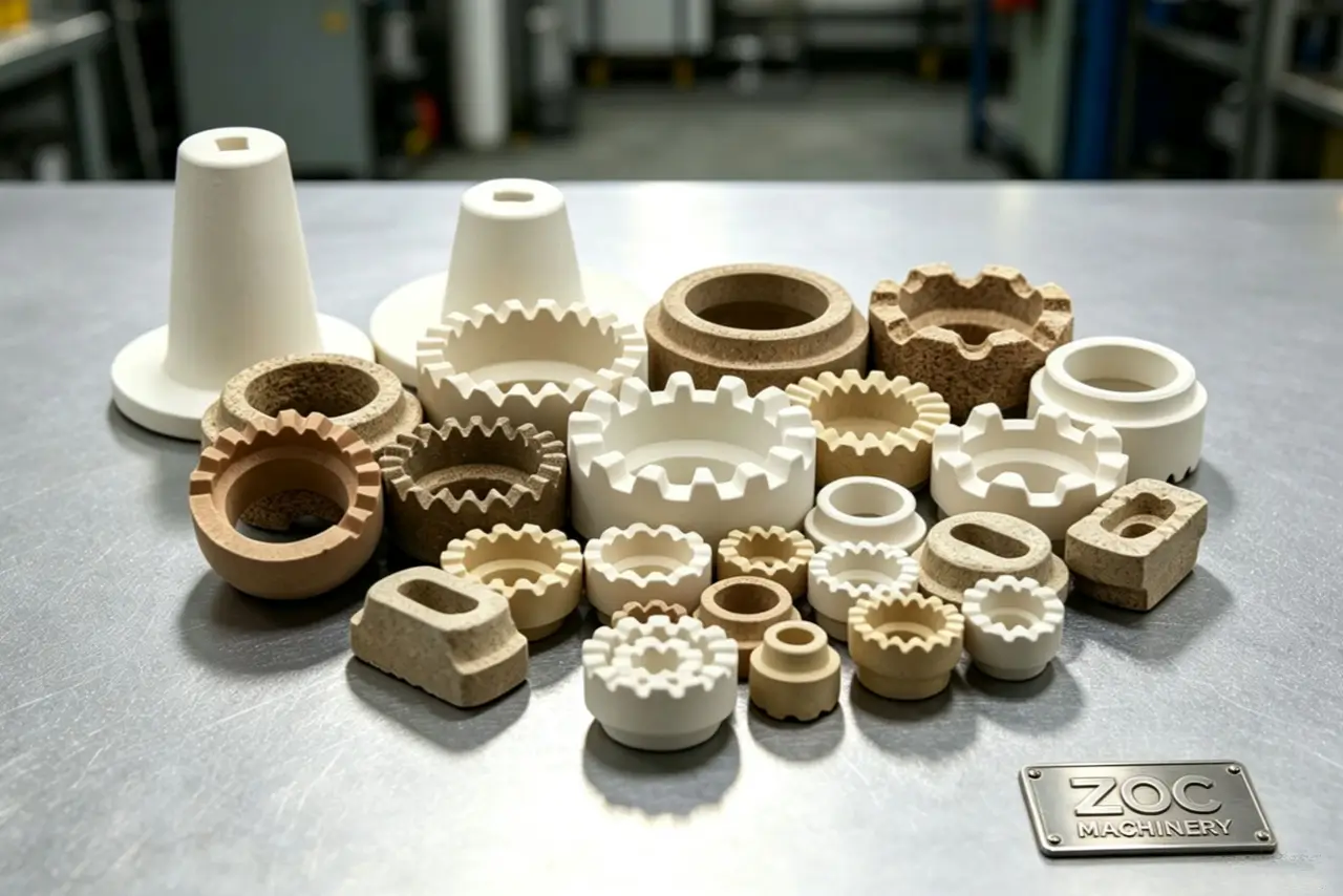
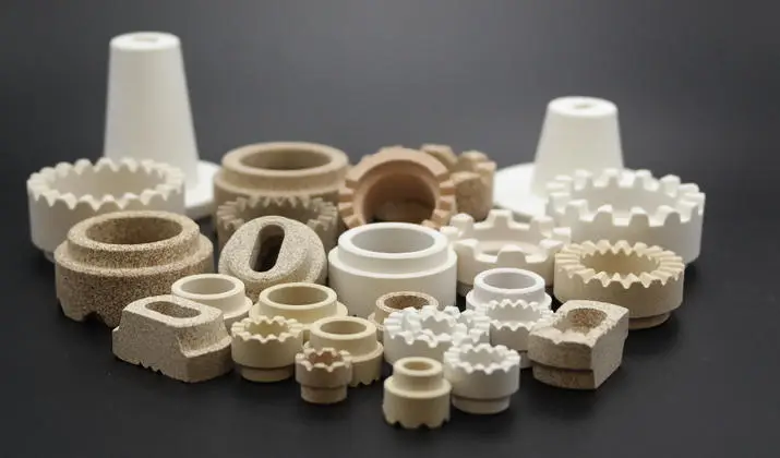
Some drawn arc studs have an aluminum ball at the weld end. The matching ceramic ring (ferrule) surrounds the joint, helps contain molten metal and forms the collar. Stud design and ferrule selection vary, so check the stud specification instead of assuming every drawn arc stud has the same tip or uses the same ring.
Factory tip: use the ferrule specified for that stud and weld position. A cracked, damp or poorly seated ferrule can change the collar and the weld. Treat ferrules as single-use consumables unless the equipment procedure explicitly says otherwise.
| Drawn arc parameter | Procurement or setup question | How to confirm |
|---|---|---|
| Current and weld time | Does the power source cover the approved range? | Procedure and trial welds |
| Lift and plunge | Can the gun hold the required movement? | Gun setup and test weld |
| Stud and ferrule | Are the parts matched to the application? | Drawings and supplier data |
| Duty cycle | Can it sustain the planned rate? | Published rating and production trial |
Capacitor Discharge (CD) Stud Welding
How does CD differ from drawn arc?
Capacitor Discharge (CD) welding stores energy in capacitors and releases it in a short pulse through a small weld end. It is often selected for smaller studs on thin sheet. Standard CD applications generally do not use ceramic ferrules, but the stud tip, material and equipment mode must match. The shorter thermal cycle can reduce distortion; it does not guarantee a mark-free reverse face.
Why use CD on thin sheet?
A suitable CD process can attach threaded studs or pins without a through-hole. Whether the back remains acceptable depends on sheet thickness, surface finish, stud size and settings. If appearance matters, weld samples made from the actual coated or polished material and inspect both sides before approval.
| CD setup | Contact mode | Gap mode |
|---|---|---|
| Stud position before firing | Stud touches the workpiece | Stud starts above the workpiece |
| Selection | Check stud and machine instructions | Check stud and machine instructions |
| Reverse-face finish | Qualify on sample sheet | Qualify on sample sheet |
Materials Used in Stud Welding
Can you join dissimilar metals?
Material pairing affects weldability and corrosion performance. Carbon steel to carbon steel is a common starting point. Stainless studs on carbon steel and other mixed-metal combinations need a qualified process and a corrosion review. Direct aluminum-to-steel arc welding is not an ordinary substitute for a designed transition joint.
Working with aluminum alloys
Aluminum oxide and surface contamination can interfere with the joint. Check the exact alloy and temper, clean the weld area as the procedure requires, and make test welds on production material. A blanket rule that one alloy series always gives the strongest stud weld, or that every aluminum CD job needs argon, is unreliable.
| Stud and base material | First qualification check |
|---|---|
| Carbon steel to carbon steel | Grade, thickness, coating and procedure |
| Stainless steel to steel | Weldability and corrosion exposure |
| Aluminum alloy to aluminum alloy | Exact alloys, surface preparation and sample weld |
| Aluminum to steel | Engineered joining method, not an assumed direct arc weld |
Safety During Stud Welding
Electrical and stored-energy hazards
Inspect insulation, leads and work clamps before use. Keep the equipment dry and follow the manufacturer’s isolation procedure before opening a power unit. CD equipment can retain stored electrical energy after power is switched off; only trained personnel should service it under the prescribed discharge and lockout steps.
Arc light, hot metal and fumes
Select eye and face protection for the actual process and current, following the applicable safety rules and equipment instructions. Protect nearby workers from direct arc light. Use appropriate clothing, gloves and ventilation or fume controls for the material and coating being welded. Do not rely on one fixed lens shade for every stud welding job.
| Hazard | Practical control |
|---|---|
| Electric shock and stored energy | Inspect cables; isolate and discharge before service |
| Arc radiation and hot metal | Suitable eye/face protection, clothing and screens |
| Fumes | Assess material/coating and use required ventilation |
Common Stud Welding Defects and Troubleshooting
Why does a stud fail a test?
A failed test can result from low or excessive energy, a dirty surface, wrong stud or ferrule, poor fit-up, a loose return lead or a gun movement problem. Record the failure and check the approved setup before changing current or time. A larger setting can create a different defect rather than fix the first one.
What causes a one-sided collar?
Arc blow can deflect the arc toward one side, especially near plate edges or with an uneven return-current path. Gun angle and ferrule seating can produce a similar appearance. Try an approved change to return-lead position after identifying the cause; dual leads can help some layouts, but cannot eliminate every case of arc blow.
Factory quality check: inspect the collar after the ferrule is removed, then apply the mechanical tests required by the job. A neat collar is useful evidence of the cycle, not proof that the weld has passed.
| Visible symptom | Check before adjusting settings |
|---|---|
| Incomplete collar | Surface, ferrule, current path and procedure |
| One-sided collar | Gun angle, return-lead layout and plate edge |
| Excess spatter or undercut | Energy, plunge, stud and ferrule match |
| Failed mechanical test | Full setup and specified acceptance criteria |
Stud Welding in Modern Construction
Headed shear connectors in composite beams
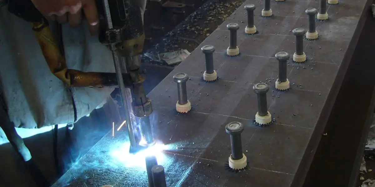
Headed headed anchor studs (shear connectors) transfer force between a steel beam and a concrete slab. Some projects weld through profiled decking; others weld directly to the beam. The structural designer sets the stud size, spacing and location. Procurement must match that drawing, including stud length after welding, material and any specified ferrules.
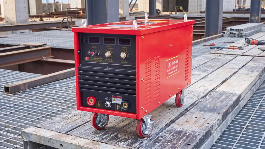
A machine such as the RSN7-2500 should be checked against the required stud sizes, duty cycle and site power. Do not translate a nominal weld-cycle time into a guaranteed daily stud count; deck access, handling and inspection affect the result.
Insulation pins and refractory anchors
Stud welding also attaches pins and anchors for insulation or refractory linings in vessels, ducts and other equipment. These parts have different geometry and service temperatures from headed shear studs. Ask for the correct fastener drawing and service requirements before choosing the process.
Automation and Portable Equipment
Automated positioning and weld records
An automated line can reduce placement variation when the part repeats. Compare positional tolerance, feeding reliability, changeover time and the weld data actually recorded by the proposed system. A supplier’s headline speed or accuracy is useful only if it is demonstrated on your component.
Portable systems for field work
Portable inverters and some battery-powered units may suit remote jobs, within their published stud-size and duty-cycle limits. Check input supply, battery capacity, cable length, access and the site procedure. A small CD unit does not replace a structural drawn arc system just because both are portable.
What B2B Buyers Should Specify
Send the supplier the stud drawing, base-metal grade and thickness, coating, weld position, expected production rate, site power and acceptance criteria. Request the machine and gun configuration, compatible studs and ferrules, a demonstration on representative material, spare-part list and documented service support.
ZOC Machinery can quote the system and consumables against that information. Contact our technical engineering team today for expert guidance with your drawing and production target so the recommendation can be checked on an actual part.
Frequently Asked Questions
Can studs be welded through paint or galvanized steel?
Paint generally needs to be removed from the weld location unless a qualified procedure specifically permits it. Through-deck welding across galvanized decking is a distinct, engineered application; use the approved stud, deck, equipment and test procedure.
How should a stud weld be tested?
Use the inspection and mechanical tests in the governing procedure and project specification. A bend test may be required, but the angle, sampling rate and acceptance criteria vary. Record the result rather than treating a shiny collar as a pass.
Can ceramic ferrules be reused?
Ceramic ferrules are normally single-use consumables. Heat, cracking or contamination can change how the next weld is contained. Order the matching quantity for the planned studs and trial welds.
What should be checked for portable field welding?
Check the power source’s process and stud range, available site power, cable length, duty cycle and environmental limits. Qualify the setup on the material and position used on site.
Can a dual return lead eliminate arc blow?
It can improve the current path on some workpieces, but it is not a universal cure. Check plate geometry, magnetism, lead placement, gun angle and ferrule seating, then follow the approved corrective procedure.