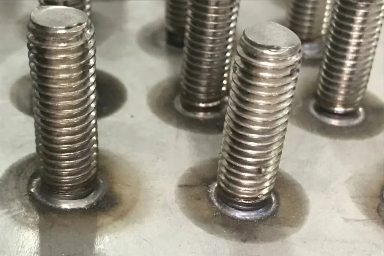
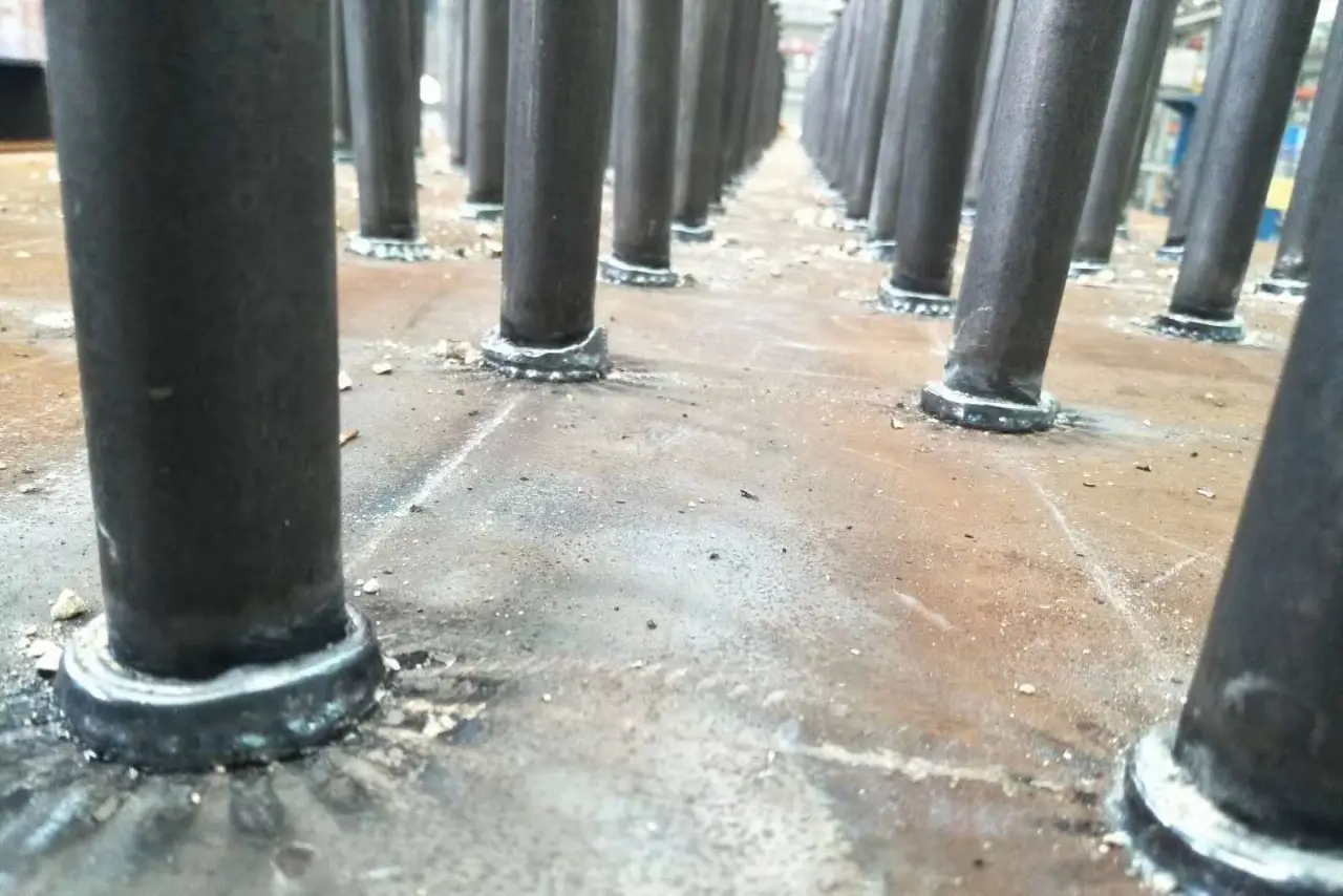
Stud welding is a high-speed metal fastening process that creates a permanent, high-strength bond between a metal stud and a workpiece by using an electric arc to melt both components. When your production line faces inconsistent results or failed pull tests, you need immediate, technical solutions to restore efficiency. This comprehensive guide from zocmachinery.com provides the expert analysis required to diagnose and resolve the most common issues found in industrial fabrication. By understanding the root causes of weld failure, you can optimize your equipment settings and ensure every fastener meets the highest structural standards.
Why is your stud welding producing weak joints?
Your stud welding joints are likely weak due to insufficient energy penetration or the use of incompatible base materials. If the weld fails under minimal mechanical stress, you must immediately verify that your power source is delivering the correct amperage and timing for the specific stud diameter.
Are you using the wrong power settings?
You must calibrate your controller to match the precise requirements of the stud diameter and material thickness. Insufficient voltage results in a shallow weld pool that fails to fuse the stud base to the parent metal effectively.
The reality is this: If your energy settings are too low, the fusion zone will be brittle and prone to sudden fracture.
- Check the manufacturer’s recommended settings chart.
- Verify that the input power to the machine is stable.
- Monitor the weld time in milliseconds for consistency.
Key Takeaway: Correcting power parameters is the most effective way to eliminate weak joints and ensure the structural integrity of your metal assemblies.
Is material compatibility the primary issue?
You should confirm that the metallurgical properties of the stud and the workpiece are compatible for the chosen welding process. Using high-carbon steel workpieces without preheating can lead to hardening in the heat-affected zone and subsequent joint failure.
Think about it: Incompatible materials will never form a reliable molecular bond regardless of your machine’s power.
- Reference ISO 14555 for material group compatibility.
- Use low-carbon steel for the best fusion results.
- Test weldability before starting high-volume production runs.
Key Takeaway: Verifying material groups prevents brittle fractures and ensures that the chemical bond between components is permanent.
The following data provides a summary of energy-related failures and their corresponding corrective measures.
| Failure Symptom | Probable Cause | Corrective Action |
|---|---|---|
| Shallow Penetration | Low Voltage | Increase Output Power |
| Brittle Fracture | Fast Cooling | Increase Weld Time |
| Partial Fusion | Unstable Current | Inspect Power Source |
This analysis highlights that the majority of weak joints are caused by avoidable setup errors that restrict the formation of a deep weld pool.
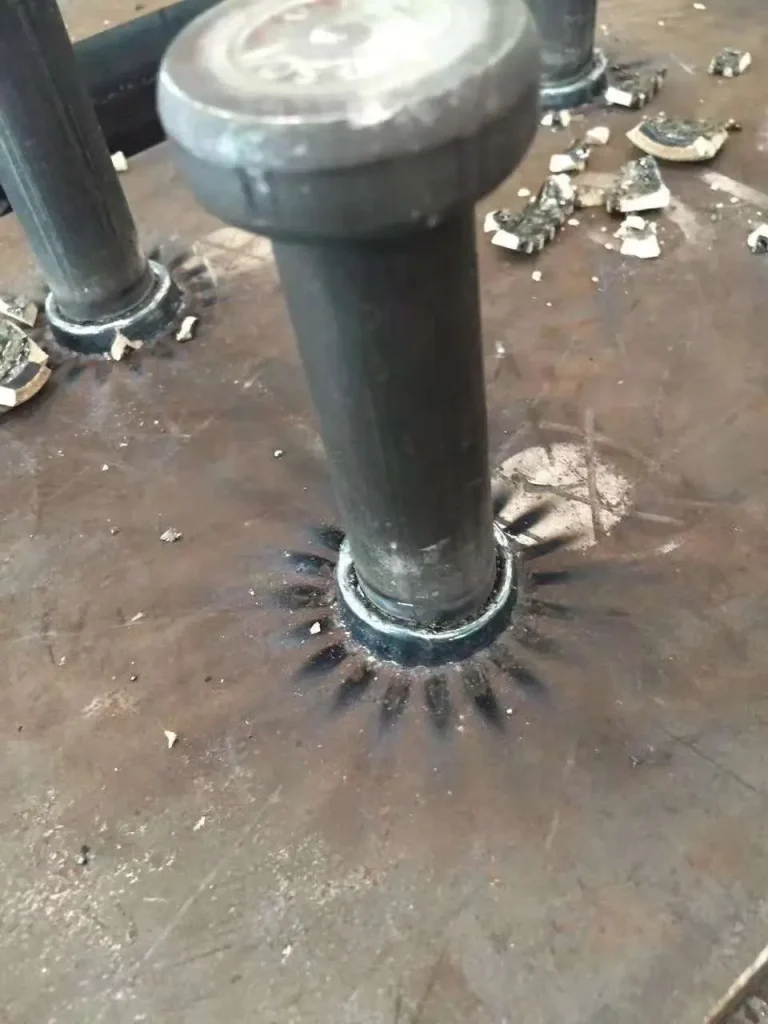
How to fix off-center collar in stud welding?
Off-center collars in stud welding occur when the welding gun is not held perpendicular to the workpiece or if the ceramic ferrule is improperly seated. To resolve this, you must ensure that the operator maintains a strict 90-degree angle and that all front-end accessories are perfectly aligned.
Is the operator holding the gun correctly?
You must train your staff to position the welding gun perfectly perpendicular to the metal surface before initiating the arc. Any slight tilt will cause the molten metal to flow toward one side, resulting in an asymmetrical collar and a weakened joint.
It gets worse: An uneven collar often masks deep undercutting on the opposite side of the stud base.
- Use a tripod or guide attachment for better stability.
- Ensure the workpiece is level and properly supported.
- Check the operator’s stance to minimize tool movement.
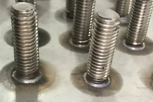
Key Takeaway: Maintaining a perpendicular tool position is critical for achieving a uniform molten collar that encapsulates the entire stud circumference.
Is the ferrule catching on the stud?
You should inspect the ceramic ferrule and the internal chuck to ensure the stud travels freely through the center of the shield. If the stud catches on the side of the ferrule during the plunge, the arc will be deflected and the collar will be misshapen.
The secret is simple: Alignment of the front-end components is just as important as the electrical settings.
- Inspect the ferrule holder for signs of wear or bending.
- Ensure the stud is centered within the ceramic shield.
- Replace worn chucks that allow the stud to wobble.
Key Takeaway: Regular mechanical alignment checks of the gun’s front end eliminate the most frequent causes of asymmetrical weld collars.
The table below summarizes the relationship between tool alignment and collar formation quality.
| Alignment Issue | Visual Result | Structural Impact |
|---|---|---|
| Tilted Gun | One-sided collar | High Risk of Failure |
| Misaligned Chuck | Offset stud base | Reduced Load Capacity |
| Worn Ferrule | Irregular bead | Poor Visual Finish |
This comparison demonstrates that precision in tool handling is mandatory for meeting industrial quality specifications for weld appearance.
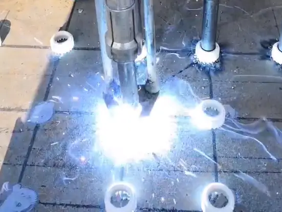
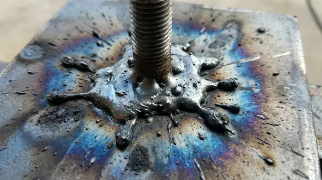
What causes excessive spatter in stud welding?
Excessive spatter during stud welding is primarily caused by excessive voltage or a plunge rate that is too violent for the molten pool. You can mitigate this by reducing the power output on your controller and adjusting the spring tension within the welding gun.
Are your voltage settings too high?
You are likely pushing too much energy through the arc, which causes the molten metal to vaporize and explode outward from the joint. Reducing the voltage will result in a calmer arc and keep the molten material concentrated within the ferrule’s containment area.
Let’s be honest: Excessive spatter increases your post-weld cleanup time and wastes valuable metal.
- Lower the voltage settings in small increments.
- Monitor the sound of the arc for a smooth “hiss.”
- Check the stud diameter against the recommended voltage.
Key Takeaway: Fine-tuning your energy output creates a cleaner work environment and protects the surrounding workpiece from surface damage.
Is the plunge rate too aggressive?
You should check if the spring pressure in the gun is forcing the stud into the weld pool with too much speed. If the stud hits the molten metal too hard, it will splash the material out of the collar zone, leaving an incomplete bond.
Here is the deal: The mechanical “plunge” must be a controlled movement rather than a violent impact.
- Loosen the internal spring tension of the welding gun.
- Adjust the hydraulic or pneumatic damper settings.
- Observe the stud entry speed during test welds.
Key Takeaway: Controlling the mechanical speed of the stud entry is essential for maintaining a full and regular molten collar.
The following table outlines the factors that contribute to spatter and how to manage them.
| Variable | High Spatter Cause | Optimization Step |
|---|---|---|
| Arc Voltage | Excessive energy | Reduce by 10-15% |
| Spring Pressure | Violent plunge | Soften the tension |
| Surface Condition | Oil or Grease | Clean with solvents |
This data shows that a combination of electrical and mechanical adjustments is required to minimize spatter and improve weld cleanliness.
Can wet ferrules ruin your stud welding results?
Wet ferrules will consistently ruin your stud welding results by introducing hydrogen and oxygen into the arc, leading to extreme porosity and brittle joints. You must ensure that all ceramic consumables are stored in a dry, temperature-controlled environment before they are used on the production floor.
Why does moisture cause weld failure?
You are introducing water vapor into a high-temperature environment, which breaks down into gases that get trapped inside the cooling metal. This results in a “Swiss cheese” internal structure that significantly reduces the tensile strength of the weld.
Believe it or not: Even a small amount of humidity can cause a batch of ferrules to fail inspection.
- Store ferrules in sealed plastic containers.
- Use a drying oven if ferrules have been exposed to moisture.
- Discard any ferrules that show visible dampness or discoloration.
Key Takeaway: Maintaining dry consumables is a non-negotiable requirement for achieving high-density welds that pass rigorous mechanical testing.
How do you identify moisture-related defects?
You can identify these issues by looking for tiny holes in the surface of the weld collar or a dull, greyish appearance of the metal. If a bend test result shows a clean fracture with internal voids, moisture contamination is the most likely culprit.
Keep this in mind: A porous weld may look acceptable on the surface but will fail under load.
- Perform a macro-etch test to reveal internal porosity.
- Look for a “frothy” appearance in the molten metal.
- Check the storage area for signs of condensation.
Key Takeaway: Visual and mechanical inspections allow you to catch moisture issues before they lead to catastrophic structural failure in the field.
The table below compares the characteristics of welds made with dry versus contaminated ferrules.
| Condition | Visual Finish | Internal Quality |
|---|---|---|
| Dry Ferrule | Bright & Shiny | Solid / High Density |
| Wet Ferrule | Dull / Greyish | Porous / Weak |
| Damaged Ferrule | Irregular Shape | Unreliable Fusion |
This analysis confirms that consumable storage conditions directly influence the mechanical properties of the final weld.
Why does burn-through happen in stud welding?
Burn-through in stud welding happens when the heat energy is too high for the thickness of the parent material, causing the arc to pierce entirely through the plate. You can prevent this by reducing the weld time on your controller or by switching to a Capacitor Discharge process for thinner gauges.
Is the plate thickness insufficient?
You must follow the recommended ratios for stud diameter to base metal thickness to avoid melting the back side of the workpiece. If the plate is too thin to dissipate the heat, the arc will create a hole rather than a stable weld pool.
The kicker is: Thin materials require a much faster discharge of energy to prevent heat saturation.
- Verify the parent metal thickness with calipers.
- Use a copper heat sink behind the welding point.
- Ensure the stud diameter does not exceed the plate’s thermal limit.
Key Takeaway: Matching the welding process to the material thickness is the only way to avoid damaging thin precision components.
Are your timer settings set too long?
You should check the weld time settings on your power source to ensure the arc is not active for longer than necessary. Even a few extra milliseconds of arc time can transfer enough heat to cause a complete burn-through on sheet metal.
Look at it this way: Precision timing is the difference between a perfect weld and a destroyed workpiece.
- Reduce the weld time in small millisecond increments.
- Check the “hot plunge” settings on your machine.
- Monitor the rear of the plate for heat discoloration.
Key Takeaway: Calibrating your machine’s timer for each specific application prevents costly material waste and production delays.
The summary table below provides guidance on preventing burn-through across different material gauges.
| Plate Thickness | Suggested Process | Mitigation Strategy |
|---|---|---|
| < 1.5mm | Capacitor Discharge | Lower the Voltage |
| 2mm – 4mm | Short Cycle Arc | Reduce Weld Time |
| > 5mm | Standard Drawn Arc | Follow Chart Settings |
Proper energy management ensures that you achieve a high-strength bond without compromising the integrity of the base material.
Is arc blow affecting your stud welding quality?
Arc blow affects stud welding quality by using magnetic fields to pull the electric arc away from its intended path, leading to uneven fusion. This phenomenon is particularly common when welding near the edges of a plate or on large, complex steel structures.
How do you diagnose arc blow issues?
You will observe that the weld pool is consistently pushed to one side of the stud, regardless of how you orient the welding gun. This is a clear sign that the magnetic field generated by the current is interacting with the metal mass to deflect the arc.
Now: Arc blow causes significant porosity and lack of fusion on the side where the arc was repelled.
- Look for “blown” metal that has moved to one side.
- Check if you are welding near a heavy corner or edge.
- Monitor for irregular arc sounds during the cycle.
Key Takeaway: Identifying magnetic interference early allows you to adjust your grounding setup before wasting more materials.
What are the best methods to counter arc blow?
You can solve this problem by using dual grounding clamps placed on opposite sides of the welding area to balance the magnetic field. Moving the grounds further away from the weld site can also help stabilize the arc path for a more centered collar.
The results are clear: Balanced grounding creates a stable environment for a perfectly uniform weld.
- Attach two ground cables at equal distances from the stud.
- Place extra steel blocks near the weld to act as magnetic bridges.
- Ensure the grounds are attached to clean, bare metal.
Key Takeaway: Strategic placement of ground clamps is the professional technique for neutralizing arc blow in challenging environments.
The table below outlines the primary causes of arc blow and their corresponding technical remedies.
| Cause of Interference | Resulting Defect | Recommended Remedy |
|---|---|---|
| Edge Proximity | Arc Deflection | Add a Run-off Tab |
| Single Ground Path | Asymmetrical Bead | Use Dual Grounding |
| Large Metal Mass | Poor Penetration | Reposition Grounding |
Solving magnetic arc interference ensures that your fasteners are as strong as the materials they are designed to join.
How to resolve porosity in stud welding seams?
Resolving porosity in stud welding seams requires the elimination of surface contaminants and the verification of proper shielding gas flow. You must ensure that the welding zone is free from oil, rust, paint, and moisture that can vaporize and create gas pockets in the molten metal.
Is surface preparation being neglected?
You must grind the welding area down to bright, bare metal to ensure that no foreign substances contaminate the molten pool. Even invisible residues like thin oil films can produce enough gas to create significant internal porosity.
Don’t ignore this: A clean surface is the foundation of every high-quality industrial weld.
- Use a wire brush or grinder to remove mill scale.
- Clean the area with a fast-evaporating solvent.
- Ensure the studs themselves are clean and free of oil.
Key Takeaway: Rigorous surface preparation is the most cost-effective way to prevent porosity and ensure a dense, high-strength bond.
Is your shielding gas flow correct?
You should check your gas regulator and lines to ensure that the shielding gas is reaching the arc at the required flow rate. If the gas coverage is insufficient, atmospheric nitrogen and oxygen will enter the weld pool and cause surface-breaking pores.
The reality is: Windy or drafty workspaces can blow your shielding gas away before it can protect the weld.
- Set the flow rate according to the machine’s specifications.
- Use a wind shield if welding in open-air environments.
- Inspect the gas hose for leaks or blockages.
Key Takeaway: Reliable gas shielding protects the molten metal from the atmosphere and is essential for producing high-integrity welds.
Refer to the summary table below for managing porosity and gas-related weld defects.
| Source of Porosity | Symptom | Corrective Action |
|---|---|---|
| Surface Rust | Internal Voids | Grind to Bright Metal |
| Low Gas Flow | Surface Holes | Increase Regulator Setting |
| Moisture | Greyish Brittle Weld | Dry the Consumables |
Eliminating these variables will consistently produce the high-density, high-strength welding joints required for structural applications.
Why is the plunge rate vital for stud welding?
The plunge rate is vital for stud welding because it controls how the stud enters the molten metal pool before the material begins to solidify. You must calibrate the mechanical speed of the welding gun to ensure the stud is seated firmly without splashing the metal out of the ferrule.
What are the dangers of a slow plunge?
You will face “cold plunge” issues if the stud moves too slowly, allowing the molten pool to cool before the stud can fully penetrate. This results in a weak surface-level bond that will fail a standard hammer or bend test.
It gets worse: A slow plunge often fails to purge the impurities from the center of the weld.
- Increase the spring tension in the welding gun.
- Check the internal shaft for friction or debris.
- Ensure the chuck is holding the stud securely.
Key Takeaway: A fast and crisp plunge is necessary to ensure the stud becomes a permanent, molecular part of the base material.
How do you optimize the damper settings?
You should use the gun’s damper to fine-tune the final impact of the stud into the molten metal. The goal is to achieve a firm seat that creates a full, regular collar without the violent splashing that leads to excessive spatter.
Here is the secret: The “plunge” should be a singular, smooth motion that feels solid to the operator.
- Adjust the damper dial in small increments.
- Listen for a solid “thud” rather than a metallic “clack.”
- Verify that the plunge distance is consistent across multiple welds.
Key Takeaway: Mastering the mechanical timing of your gun’s plunge is the final step in achieving professional-grade weld quality.
The table below details the impact of different plunge rates on the final weld integrity.
| Plunge Speed | Resulting Quality | Required Adjustment |
|---|---|---|
| Too Slow | Lack of Fusion | Increase Spring Pressure |
| Too Fast | Excessive Spatter | Increase Damping |
| Consistent | Full Penetration | Maintain Equipment |
Managing these mechanical variables ensures that every weld meets both visual and structural engineering requirements.
Does improper grounding fail your stud welding?
Improper grounding fails stud welding by creating high electrical resistance that fluctuates the arc intensity and prevents stable fusion. You must ensure that your ground clamps are attached to clean, bare metal as close to the welding site as possible to minimize power loss.
Is your ground clamp attached to a coated surface?
You are likely experiencing arc start failures because the current cannot flow through non-conductive coatings like paint, rust, or powder. You must grind a dedicated spot on the workpiece to reveal bright metal for the ground clamp to ensure a perfect circuit.
Think about this: A weak ground is the most common cause of “phantom” machine errors and inconsistent welds.
- Clean the grounding point with a grinder or wire brush.
- Ensure the clamp has a strong mechanical grip on the metal.
- Inspect the ground cable for frayed or broken copper strands.
Key Takeaway: Establishing a solid electrical connection is the fundamental first step for every successful welding cycle.
Why is ground proximity so important?
You should minimize the distance between the ground clamp and the welding point to reduce the voltage drop across the workpiece. If the current has to travel through long distances or multiple bolted joints, the arc will be weak and penetration will be insufficient.
The truth is this: The path of least resistance determines the success of your weld penetration.
- Place ground clamps within one meter of the weld site.
- Use heavy-duty copper cables for better conductivity.
- Avoid grounding through bearings or mechanical hinges.
Key Takeaway: Proximity and cleanliness are the two golden rules for grounding that every professional operator must follow.
The table below summarizes the best practices for industrial grounding in fabrication environments.
| Grounding Check | Error to Avoid | Best Practice |
|---|---|---|
| Surface Condition | Clamping on paint | Grind to bare metal |
| Distance | Grounding too far | Keep within 3 feet |
| Cable Health | Using frayed wires | Replace damaged cables |
High-quality grounding ensures that 100% of the energy from your power source is used to create the weld.
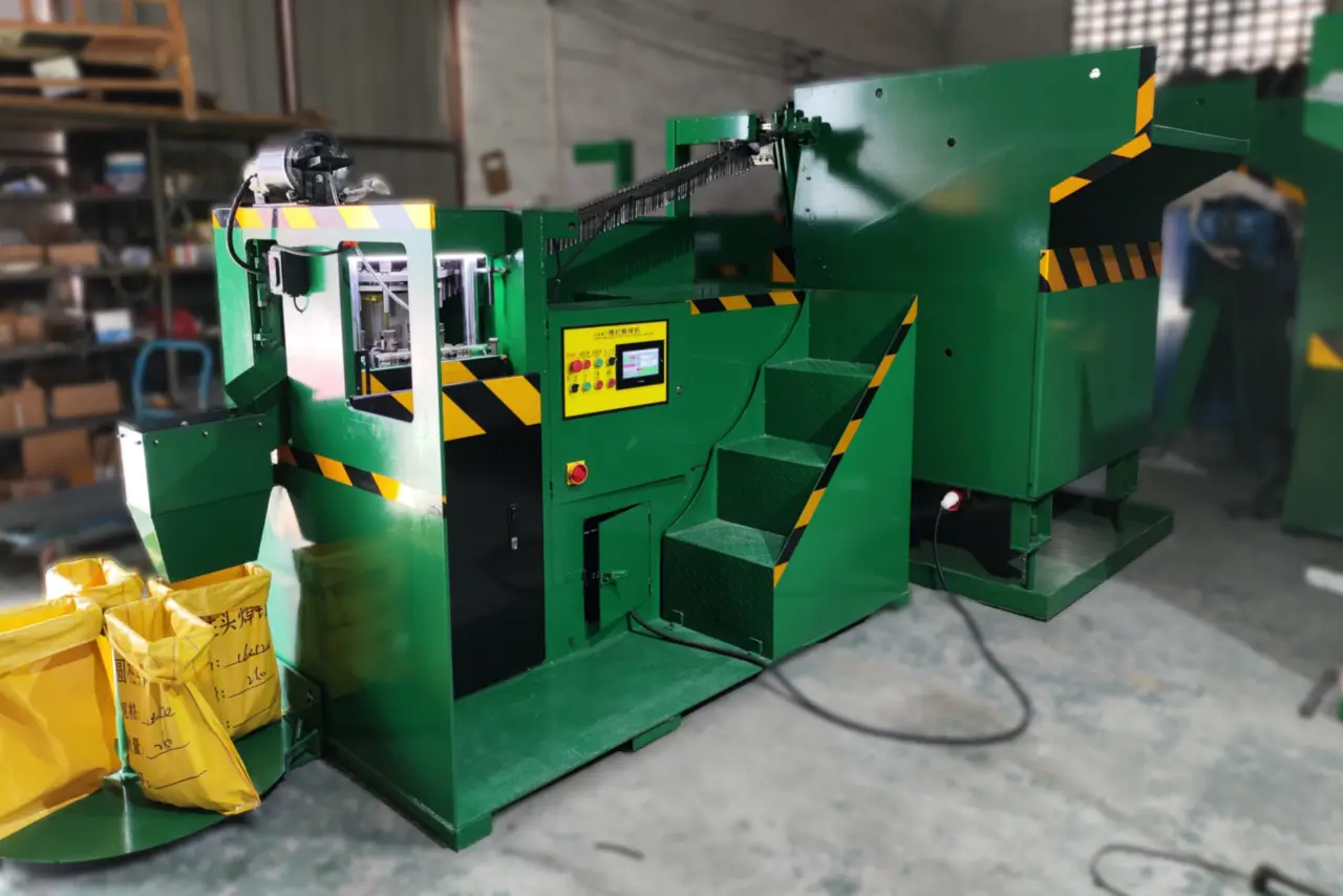
How to maintain your stud welding equipment?
Maintaining your stud welding equipment requires a regular schedule of cleaning the gun’s internal components and inspecting the power cables for heat damage. You should perform daily, weekly, and monthly checks to prevent unexpected downtime and maintain the highest levels of weld consistency.
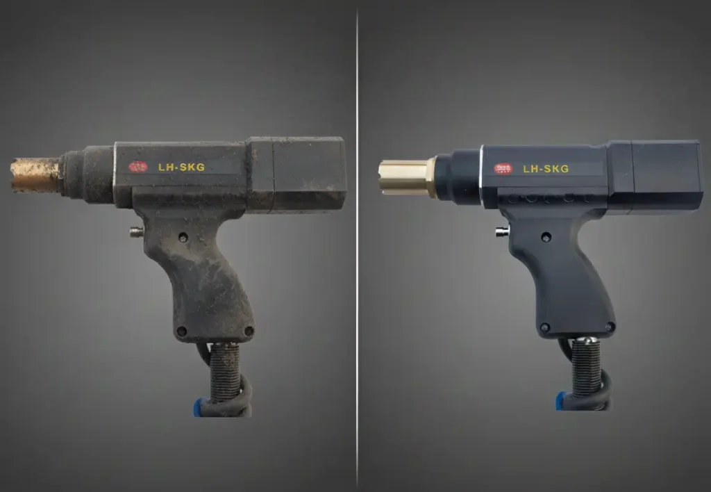
How often should you clean the chuck and gun?
You must clean the internal shaft and the copper chuck of the welding gun daily to remove metal dust and carbon buildup. If these parts are dirty, the stud will not release properly, leading to mechanical jams and failed cycles.
Keep in mind: A clean tool is a reliable tool that produces predictable results under heavy load.
- Use compressed air to blow out dust from the gun housing.
- Clean the chuck with a fine wire brush to ensure good contact.
- Lubricate the sliding parts according to the manual.
Key Takeaway: Preventive daily cleaning is the easiest way to avoid the mechanical failures that can halt your entire production line.
When should you replace the power cables?
You should inspect all power and control cables weekly for signs of heat damage, cuts, or loose terminal connections. Damaged cables are a safety hazard and cause significant power fluctuations that ruin the quality of your fasteners.
The bottom line is: If the cable connectors feel hot to the touch, they are loose and need immediate tightening.
- Check the cable insulation for cracks or burns.
- Ensure all terminal nuts on the machine are tight.
- Replace any cable that shows exposed copper or internal breaks.
Key Takeaway: Ensuring your electrical delivery system is in top condition protects both your equipment and your operators.
The table below provides a comprehensive maintenance schedule for industrial welding systems.
| Component | Daily Task | Monthly Task |
|---|---|---|
| Welding Gun | Clean Chucks | Inspect Internal Springs |
| Power Source | Wipe Down Case | Blow out Interior Dust |
| Ground Cables | Check Clamps | Test for Resistance |
Consistent maintenance is the only way to ensure your equipment lasts for decades of heavy service in demanding environments.
Conclusion
Mastering the technical nuances of the welding process is the key to achieving industrial-grade reliability and structural safety in your fabrication projects. From calibrating your energy settings to implementing strategic grounding and maintaining your equipment, every step you take directly influences the quality of your finished products. By applying the troubleshooting solutions provided in this guide, you can eliminate common defects and optimize your production efficiency. We are committed to providing the high-performance machinery and technical expertise you need to lead the market. Please contact us today to discuss your specific requirements or to explore our latest automated solutions. Innovation drives our engineering; your success defines our mission.
Frequently Asked Questions
Can I weld studs onto a stainless steel surface?
Yes, you can weld studs onto stainless steel, but you must use stainless steel studs and verify that the base material is clean. You should also adjust your voltage settings, as stainless steel has different electrical resistance than mild steel.
What’s the best way to determine if a weld is sound?
The best way to determine weld integrity is through a combination of visual inspection and a 15-degree bend test. A sound weld will have a bright, full collar and will not show any cracking when bent using a standardized bending bar.
How do I know if my weld time is too short?
You will know the weld time is too short if the stud fails to penetrate the parent material and snaps off easily, showing a flat, un-melted surface. You should increase the time in 10ms increments until a full molten pool is formed.
Can I reuse ceramic ferrules if they look clean?
No, you should never reuse ceramic ferrules because they are designed as single-use consumables that degrade during the arc. Reusing a ferrule will result in poor gas containment and significant porosity in the subsequent weld.
How do I know if my ground cable is failing?
You can tell a ground cable is failing if the machine displays “No Arc” errors or if the cable connectors become excessively hot during use. High resistance in a failing cable will cause inconsistent weld strength and unpredictable machine behavior.