Stud welding quality is the result of a matched stud and base metal, a controlled welding cycle, and inspection against a stated acceptance standard. A neat fillet can reveal useful information, but it cannot prove the strength of a hidden joint. In industrial fabrication, the practical question is whether the welds meet the drawing and the qualified procedure, consistently, across the production run.
Why stud welding quality matters for safety
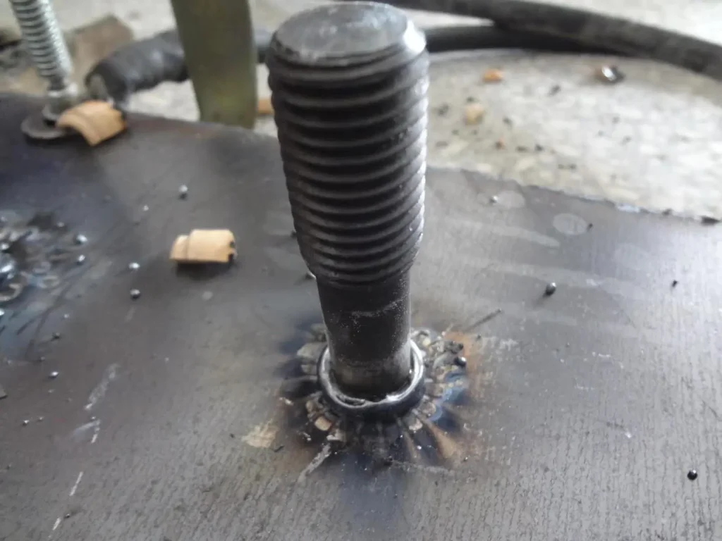
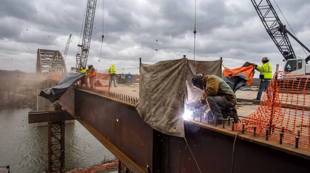
A stud may carry a bracket, insulation system, electrical connection, or structural load. The consequence of a failed weld depends on that application. For a bridge shear connector, the design and inspection requirements are different from those for a small enclosure stud. Define the duty and acceptance criteria before welding so that operators and inspectors know what a pass means.
Start with the joint requirement
- Confirm the stud type, material, dimensions, and location on the drawing.
- Identify the load and service conditions, including vibration, corrosion, and temperature where relevant.
- Use the welding procedure and inspection plan required by the contract or product specification.
- Record the setup and the results of required production checks.
This approach gives the fabricator evidence for a batch of welds rather than relying on one good-looking sample.
| Quality question | Evidence to use | Why it matters |
|---|---|---|
| Is the right stud installed? | Drawing and batch identification | Fit and design load |
| Was the joint made as specified? | Procedure and setup record | Repeatability |
| Did it pass inspection? | Visual and required test results | Acceptance and traceability |
Fusion and penetration in a stud weld
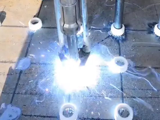
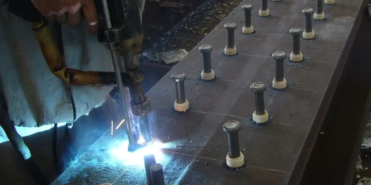
Drawn-arc welding melts the stud end and a local area of the base metal before the stud plunges into the molten pool. The stud welding machine must deliver the programmed output, but the stud tip, work surface, return path, and gun setup also affect the joint. There is no universal penetration depth that defines a pass for every stud diameter and material.
What can and cannot be seen
A visual check may show an incomplete fillet, severe spatter, tilt, or other surface defect. It cannot measure fusion through the weld cross-section. Procedure trials and the tests specified for the job provide that evidence. If a trial weld fails, review the whole setup before changing current or time alone.
Our arc stud welding process guide follows the lift, arc, plunge, and solidification sequence.
| Observation | Possible issue to investigate | Verification |
|---|---|---|
| Incomplete collar | Heat, alignment, or shielding | Procedure review and trial weld |
| Stud separates at interface | Inadequate joint formation | Required mechanical or section test |
| Excessive distortion | Heat input or base thickness | Sample on actual material |
Visual signs worth checking
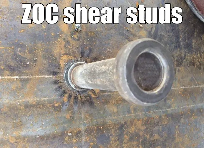
Inspect the weld against the project criteria for fillet shape, stud position, cracks, undercut, and visible pores. A uniform collar can support a good process assessment, but it is not a substitute for required testing. Surface color alone is particularly unreliable: oxidation, material, and cleaning change the appearance.
Treat the pattern as a clue
An uneven fillet may point to gun angle, arc blow, ferrule seating, or inconsistent surface condition. Repeated defects in one location may point to the return-lead arrangement or access. Document the pattern, correct the cause, and recheck on trial welds before production continues.
For a field checklist of symptoms and likely causes, see common stud welding problems and solutions.
| Visual check | What it may reveal | Limit |
|---|---|---|
| Fillet shape | Missing or uneven weld metal | Does not prove internal fusion |
| Stud position | Placement or gun-alignment error | Tolerance comes from drawing |
| Surface defects | Cracks, pores, or undercut | Acceptance comes from specification |
How the gun affects weld quality
The stud welding gun positions the stud, controls lift and plunge movement, and helps the operator hold the stud square to the work. Worn chucks, a sticking mechanism, loose foot assembly, or damaged cables can change the cycle even when the power source display has not changed. Check the gun to the manufacturer’s instructions and the approved procedure.
Check movement and fit before adjusting power
- Confirm the chuck grips the specified stud without excessive play.
- Check lift, plunge travel, and foot contact as applicable to the gun.
- Keep the gun square and steady until the weld has set.
- Inspect cable connections and replace worn parts before they affect production.
The stud welding gun guide explains how its moving parts affect the cycle.
| Gun part | Quality effect | Practical check |
|---|---|---|
| Chuck and holder | Stud position and electrical contact | Fit and wear |
| Lift and plunge mechanism | Arc gap and joining movement | Free travel and approved setting |
| Foot or stand | Angle and working distance | Seating and alignment |
| Cables and connectors | Current path | Damage and secure connection |
Base metal and surface preparation
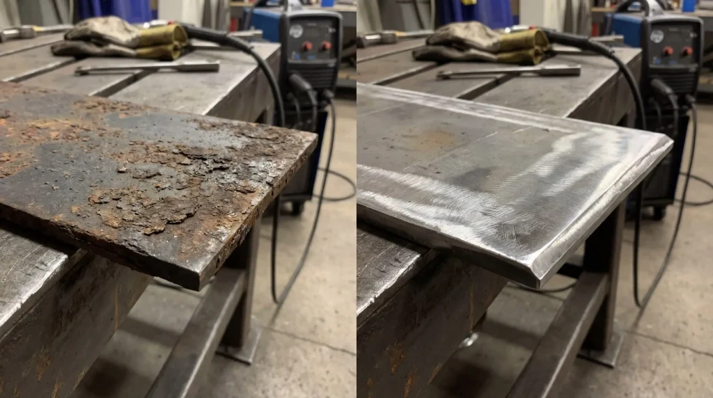
Oil, moisture, rust, scale, and coatings can affect arc initiation and the weld pool. Clean and prepare the actual weld location as the qualified procedure requires. A blanket rule to grind every surface to bright metal is too broad: the required method depends on the material, coating, and process, and removing a coating can create its own safety and corrosion questions.
Match the stud to the plate
Confirm the stud and base-metal grades, not just their visible appearance. Dissimilar combinations may be possible with a qualified procedure and suitable corrosion plan. In capacitor-discharge work, stud welding quality also depends on a clean surface and the correct ignition-tip geometry; the linked CD defect guide covers that process specifically.
Check that the return clamp is attached to an approved clean location. Reassess the setup when the plate, coating, or cable path changes.
| Condition | Possible effect | Response |
|---|---|---|
| Oil or moisture | Porosity or unstable arc | Clean and dry as specified |
| Rust or scale | Inconsistent contact | Prepare the weld area |
| Coating or zinc layer | Process and fume changes | Follow qualified coating procedure |
| Material change | Different welding behavior | Reconfirm procedure and trials |
Verify equipment settings and condition
A setpoint on the display is useful only if the power source, cables, return path, and gun are working as intended. Check the equipment at the interval required by its manual and the site quality plan. Do not use a universal voltage tolerance or calibration interval: those values are specific to the equipment and the procedure.
What to record
- Power-source model and the accepted current, time, and program settings.
- Gun, cable, and return-lead configuration.
- Stud, ferrule or gas, and base-metal batch or specification.
- Trial-weld results after setup or a material change.
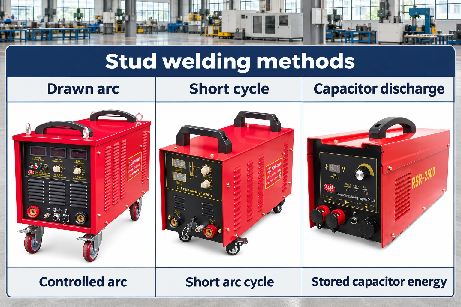
Our stud welding machine maintenance guide covers routine checks that help keep the setup stable.
| Equipment check | Reason | Reference |
|---|---|---|
| Output and controls | Confirm the programmed cycle | Machine manual and procedure |
| Cable and return path | Avoid poor contact or damage | Site inspection plan |
| Gun movement | Keep lift and plunge repeatable | Gun instructions |
| Cooling and duty cycle | Operate within machine rating | Manufacturer specification |
Ferrules and shielding
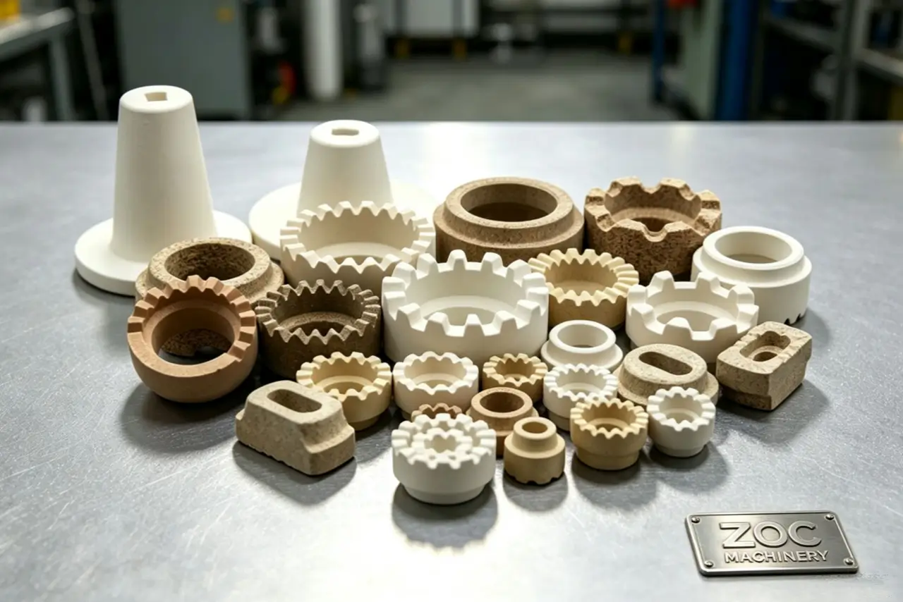
Ceramic ferrules help contain the molten metal and shape the weld collar in many drawn-arc applications. Use the ferrule matched to the stud and procedure, and keep it dry and undamaged. Other approved setups use shielding gas or a different process. The right accessories are part of the welding system, but no single ferrule is mandatory for every stud weld.
Check the whole shielding arrangement
Ferrule fit, seating, and the work surface affect the weld. Where the process uses gas, check the specified flow and delivery. The ceramic ferrule guide explains why ferrule and stud geometry need to match.
| Protection method | Where it may be used | Check |
|---|---|---|
| Ceramic ferrule | Many drawn-arc structural welds | Fit, dryness, and seating |
| Shielding gas | Approved gas-shielded procedures | Gas type, flow, and coverage |
| No separate shield | Selected short-cycle or CD setups | Procedure and material suitability |
Test and inspect welds to the specified criteria
Visual inspection is usually the first check. Bend, tensile, torque, or other tests may be required depending on the stud and governing specification. ISO 14555:2025 addresses procedure qualification and production-weld testing for arc stud welding; a structural contract may invoke AWS D1.1 or another code. The test angle, frequency, and pass criterion must come from the applicable requirement, not a generic web chart.
Use the test for its purpose
A bend test can expose a weak joint in a trial or sampled production weld, but it changes the tested stud. A torque test can be relevant to a threaded attachment only when the procedure specifies how to apply and interpret it. Visual inspection cannot confirm hidden fusion, and a single destructive test does not prove every weld in a batch.
The stud welding parameter guide explains why trial settings and inspection must be considered together.
| Method | What it checks | Acceptance basis |
|---|---|---|
| Visual examination | Visible shape, position, and surface defects | Project criteria |
| Bend test | Joint response to deformation | Specified method and sample rate |
| Tensile or torque test | Application-specific mechanical response | Drawing or qualified procedure |
| Section examination | Internal fusion in a sample | Qualification or investigation plan |
Account for base-metal thickness
A thin sheet can distort or show a mark on its reverse face; a thicker part may need different heat input. The process choice also depends on stud diameter, material, surface, and access. Capacitor-discharge welding is often considered for thin sheet, while short-cycle and drawn-arc methods cover other operating ranges. Fixed thickness cutoffs do not replace a trial on the actual workpiece.
Run the trial on production-like material
Use the same plate grade and thickness, coating, joint position, and cable arrangement planned for the job. Check weld acceptance and any reverse-side appearance requirement. If the drawing limits distortion, measure it rather than assuming the faster process prevents it.
Our CD versus drawn-arc comparison helps narrow the process choice before testing.
| Base-metal condition | Concern | Verification |
|---|---|---|
| Thin sheet | Distortion or reverse-side marking | Trial weld and appearance check |
| Heavy plate | Heat input and fusion | Procedure trial and test |
| Coated surface | Contact, fumes, and finish | Approved preparation method |
| Variable thickness | Changing weld response | Separate qualified setup if needed |
Keep quality consistent across production
Consistency means the accepted setup is reproduced and changes are caught early. Automation can hold position and timing more steadily in a suitable fixture, but it cannot correct the wrong stud, dirty metal, worn tooling, or a poor return path. Manual work also benefits from clear setup sheets, operator training, and records.
Set a practical control loop
- Approve trial welds before a production run.
- Record the machine program, gun setup, materials, and consumables.
- Inspect at the frequency required by the quality plan.
- Stop and investigate a repeated defect before it spreads through a batch.
When the process changes, repeat the checks the procedure calls for. That is more useful than quoting an unsupported percentage for automated repeatability.
| Control point | Manual station | Automated station |
|---|---|---|
| Stud supply | Operator verifies type and condition | Feeder and sensors still need checks |
| Position | Operator and fixture control it | Fixture and program control it |
| Weld cycle | Approved setup and observations | Approved program and monitoring |
| Inspection | Required visual and sample tests | Same acceptance plan, with process data |
A workable quality standard for the shop
Good stud welding quality starts with a defined joint and ends with recorded acceptance, not a promise of perfect welds. Give the crew the drawing and procedure, verify the first welds on the real material, and investigate defects before production continues. ZOC Machinery can help match the power source, gun, and consumables to the application; contact us with the stud size, base-metal grade, and required inspection standard.
Frequently asked questions
Can I judge penetration from the weld collar?
No. The collar can show visible problems, but internal fusion needs the tests required by the procedure. A sectioned trial weld may be used when qualification or troubleshooting calls for it.
What usually causes porosity?
Possible causes include contamination, moisture, and shielding problems. Inspect the material and consumables before changing settings; the actual cause should be confirmed through trials or examination.
Can I make a quality weld without a ceramic ferrule?
Yes, if the selected stud, process, and qualified procedure use shielding gas or another approved arrangement. Do not omit a ferrule from a procedure that requires one.
Can dissimilar metals be stud welded?
Some combinations can be qualified. Check weldability, the required mechanical performance, and corrosion in service rather than assuming all dissimilar pairs behave alike.
How often should I check the gun settings?
Follow the machine and gun instructions and the job quality plan. Recheck after a setup change, maintenance, or a defect trend; there is no single interval suitable for every station.