Capacitor discharge (CD) and drawn arc stud welding join a stud to metal in different ways. CD releases stored energy in a brief pulse, making it a useful choice for smaller studs and sheet metal where backside appearance matters. Drawn arc lifts the stud, maintains an arc, then plunges it into a larger molten pool; it is commonly specified for structural studs. This Capacitor Discharge vs Drawn Arc guide compares the two by material, thickness, load, finish and production setup.
Capacitor Discharge vs Drawn Arc: Where Each Fits
Start with the base metal and the job the stud must do. Our guides to Capacitor Discharge vs Drawn Arc explain each process in more detail; the comparison below helps you decide which one to test on your parts.
Start With the Base Metal
Mild steel and stainless steel can be welded with either process when the stud, surface and settings are suitable. Aluminum needs a compatible stud and a qualified procedure; neither process is a universal answer.
- Mild steel: Both processes are used; select by stud size, sheet thickness and load.
- Stainless steel: Both are possible with suitable studs, settings and surface preparation.
- Aluminum: Match the alloy, stud and shielding or CD mode to a tested procedure.
Set the Load and Finish Requirements
For a load-bearing connection, specify the required load and acceptance test before choosing the welding method. For a visible panel, check the reverse side on a sample part as well as the weld itself.
- Structural load: Follow the design specification and qualified weld procedure.
- Visible finish: Check both sides of the actual part after welding.
- Stud diameter: CD is generally used for smaller studs; drawn arc covers larger ones.
The quick comparison below is a starting point. Your plate thickness, stud size and approved welding procedure decide what is practical.
| Comparison factor | Capacitor discharge (CD) | Drawn arc |
|---|---|---|
| Typical priority | Thin sheet and finish | Larger studs and structural work |
| Reverse side | Often less marking; test first | Heat effect depends on plate and setup |
| Typical base metal | Often thin sheet | Usually thicker plate |
Base-Metal Thickness and Stud Size
Base-metal thickness and stud diameter narrow the choice in any capacitor discharge vs drawn arc comparison. CD is often used on thin sheet with small studs. Drawn arc is commonly used on thicker plate and larger studs, although some short-cycle variants cover intermediate work. Avoid treating a single thickness cutoff as a process rule.
CD on Thin Sheet
A CD pulse puts less total heat into the sheet than a typical long-cycle drawn arc weld. That can reduce distortion and reverse-side marking. It does not guarantee a flawless face: test the actual sheet gauge, coating and stud size.
- Heat input: A short CD pulse can reduce distortion on thin sheet.
- Sheet range: Confirm the exact gauge with the stud and equipment documentation.
- Finish: Inspect for marking, flash and coating damage before approval.
A high-current arc welder set for structural studs can burn through thin sheet. Check the machine’s approved range and run trial welds before production.
Drawn Arc on Thicker Plate
Drawn arc needs enough base metal to form and support the weld pool without burn-through or excessive distortion. Minimum thickness varies with stud diameter, base metal, weld time and the governing specification.
- Minimum plate: Calculate from stud size, procedure and design requirements.
- Fusion: Drawn arc forms a larger molten pool for larger studs.
- Joint qualification: Test representative samples to the applicable standard.
| Base-metal thickness | CD suitability | Drawn arc suitability |
|---|---|---|
| Thin sheet | Often suitable with small studs | Conventional long-cycle setup may distort it |
| Intermediate gauge | Check stud size and test welds | Short-cycle options may be suitable |
| Thicker plate | Possible for suitable small studs | Common for larger studs |
Weld Strength and Load Requirements
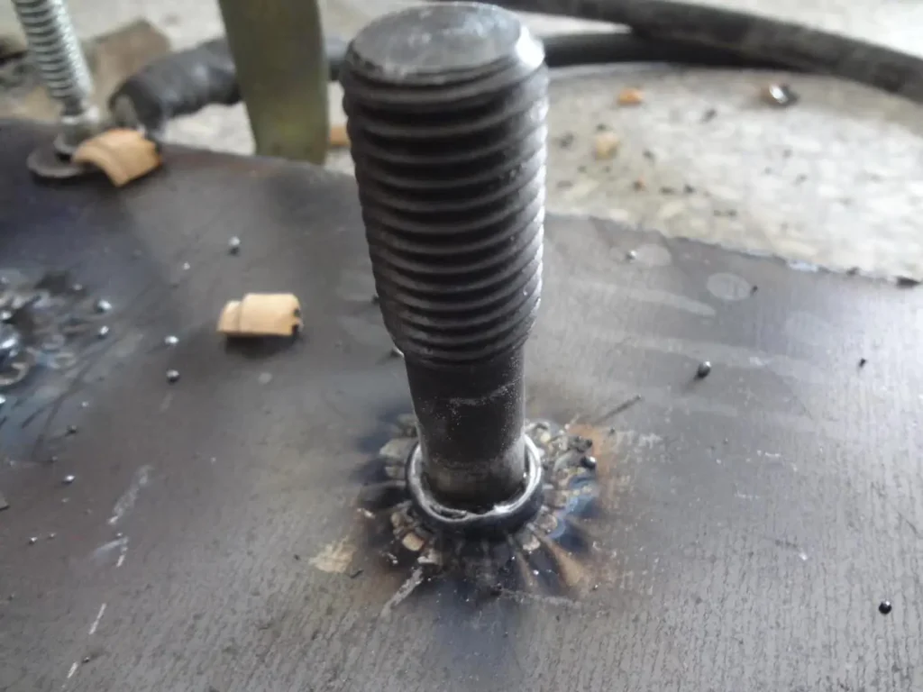
Drawn arc is widely used for structural shear connectors and larger studs because it can form a substantial fusion zone. CD is normally chosen for smaller, non-structural attachments. Neither label tells you the load capacity of a finished joint on its own.
How Drawn Arc Forms the Joint
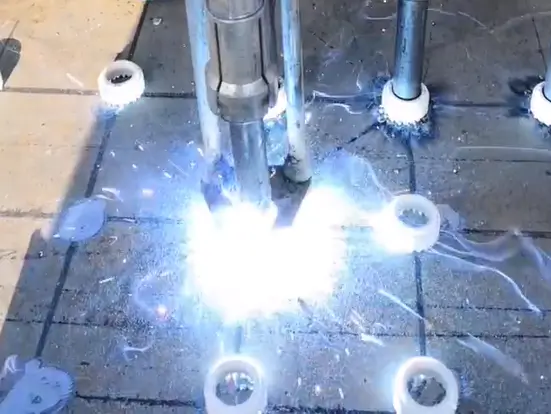
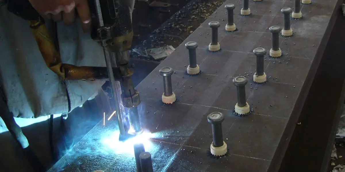
In drawn arc welding, the gun lifts the stud, the arc melts both mating surfaces, and the gun plunges the stud into the pool. Current, time, lift and plunge settings influence the resulting weld.
- Weld area: A complete, consistent fillet is one inspection point.
- Codes: Check the project specification; a process name does not certify a weld.
- Fillet: Ferrule size and gun position affect its shape.
When a CD Weld Is Strong Enough
A properly made CD weld can carry the specified load for brackets, enclosures and other light-duty fittings. Verify it with the test method and acceptance criteria for your application; do not transfer a catalog load figure to a different stud or sheet.
- Load: Obtain tested values for the exact stud and base material.
- Failure mode: The sheet, stud or weld may fail depending on the joint design.
- Torque: Test threaded attachments to the specified requirement.
| Strength factor | CD welding | Drawn arc welding |
|---|---|---|
| Fusion zone | Localized | Larger weld pool |
| Typical application | Specified non-structural attachments | Structural or larger-stud connections |
| Verification | Test the actual joint | Follow structural specification and tests |
Weld Time and Production Speed

The CD electrical pulse is measured in milliseconds. Drawn arc usually holds the arc longer to melt a larger stud and more base metal. Compare complete cycle time, including charging, positioning and ferrule handling, before estimating line output.
Why CD Cycles Are Short
CD stores energy in a capacitor bank and releases it through the stud tip. For repetitive small-stud work, positioning and recharging often matter more to throughput than the pulse duration itself.
- Pulse: The discharge itself lasts milliseconds.
- Handling: Allow the joint to cool and follow the inspection procedure.
- Throughput: Include recharge, positioning and handling in cycle-time estimates.
Why Drawn Arc Takes Longer
Drawn arc takes longer because the stud and base metal need time to form a suitable weld pool. That extra time is part of achieving the specified joint, not a defect in the process.
- Arc time: Set it for the stud and base material; do not use one universal value.
- Stages: Lift, arc formation and plunge.
- Duty cycle: Confirm the machine rating for production volume.
| Speed factor | CD welding | Drawn arc welding |
|---|---|---|
| Weld pulse or arc time | Millisecond discharge | Longer arc time; settings vary |
| Handling | Include recharge and positioning | Include ferrule handling and cooling |
| Production fit | Repetitive small-stud work | Larger studs and construction |
Welding Aluminum Studs
Aluminum is weldable by CD and by suitable drawn arc procedures. The right choice depends on alloy, stud design, thickness, shielding and required load. CD often suits small aluminum studs on thin sheet; larger aluminum drawn arc studs are also available.
What Changes With Aluminum
Aluminum conducts heat quickly and its oxide layer affects fusion. Use clean, compatible material and follow the stud and equipment maker’s settings rather than copying steel parameters.
- Heat flow: Aluminum conducts heat quickly, so setup matters.
- Finish: Trial-weld polished or coated panels before production.
- Alloy: Confirm the grade is suitable for the chosen stud and process.
A gap-mode CD gun may suit some aluminum applications, but contact and gap modes both need trial welds. Use the gun mode and setup recommended for that stud and alloy.
Set Parameters for Aluminum
Do not apply a fixed voltage increase when switching from steel to aluminum. Select starting settings from the machine and stud documentation, then confirm the weld on the production material.
- Settings: Use the machine maker’s starting values and validate on samples.
- Oxide: Clean the joint area as required by the procedure.
- Shielding: Follow the specified gas or ferrule arrangement.
| Aluminum factor | CD welding | Drawn arc welding |
|---|---|---|
| Typical use | Small studs on thin sheet | Suitable larger studs with approved procedure |
| Heat control | Short pulse; test settings | Manage arc time and shielding |
| Material check | Confirm alloy and stud compatibility | Confirm alloy, ferrule/gas and procedure |
Ferrules and Shielding
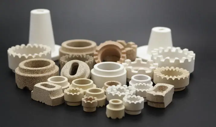
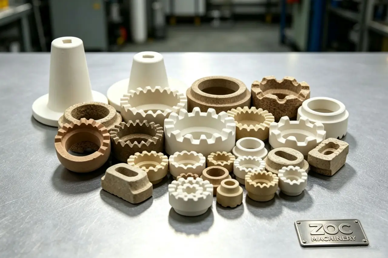
Structural drawn arc work commonly uses a ceramic ferrule to contain the molten metal and shape the fillet. Other qualified drawn arc procedures use gas shielding. CD tip-ignition work usually needs neither a ferrule nor shielding gas, but check the process specification.
What a Ceramic Ferrule Does
A correctly matched ferrule helps contain the weld pool around a drawn arc stud. Use the size and type specified for the stud; damaged or wet ferrules can affect weld quality.
- Arc protection: A ferrule can protect and contain the weld pool.
- Molten metal: The ferrule helps form the weld fillet.
- Consumable: Use a ferrule matched to the stud.
How a CD Ignition Tip Works
A CD stud has a small ignition tip at its weld end. The tip initiates the discharge and is consumed during welding. It is part of the stud design, not a substitute for surface preparation or a sound procedure.
- CD tip: The ignition tip starts the weld and is consumed.
- Supplies: Tip-ignition CD often avoids ferrule handling.
- Access: Check that the gun can reach and sit square on the joint.
| Shielding factor | CD welding | Drawn arc welding |
|---|---|---|
| Ceramic ferrule | Usually unnecessary for tip-ignition CD | Common in structural applications |
| Shielding gas | Follow the specified procedure | Used in some qualified procedures |
| Handling | Check tip and work surface | Match ferrule or gas to the stud |
Reverse-Side Appearance
CD can leave the reverse side of a thin panel cleaner than a higher-heat drawn arc weld. Marking still depends on gauge, coating, stud size and settings. Check a production-like sample if the visible face is critical.
Check the Finished Face
For enclosure panels and finished sheet-metal parts, inspect both sides after a trial weld. Heat effects can show through paint or polished metal even when the weld side looks acceptable.
- Distortion: CD can reduce it, but verify on the actual sheet.
- Coatings: Prepare the weld side and test the finished face.
- Appearance: Inspect both sides against the agreed standard.
Expect a Visible Arc-Weld Fillet
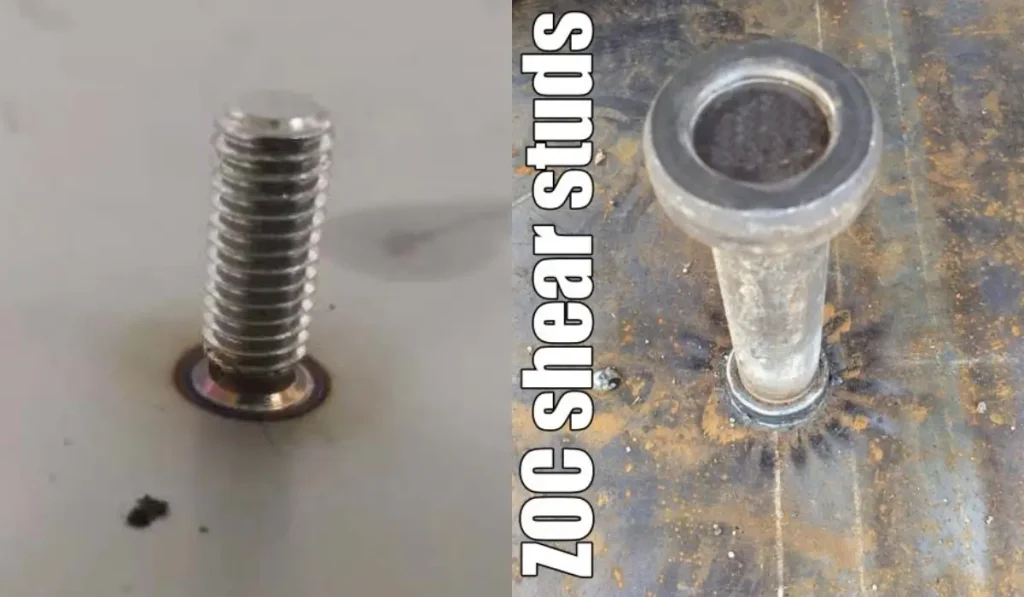
A drawn arc weld normally has a visible fillet at the stud base. On thin material, its higher heat input can also change the reverse-side appearance. On structural plate, inspect the fillet against the applicable acceptance criteria.
- Fillet: Drawn arc leaves a visible collar at the stud base.
- Plate: Thicker material can better accommodate the weld pool.
- Finish: Structural welds still need inspection.
| Appearance factor | CD welding | Drawn arc welding |
|---|---|---|
| Reverse side | Often cleaner; verify on sample | May show heat effects on thin material |
| Weld face | Small weld area | Visible fillet at stud base |
| Typical use | Enclosures and sheet-metal parts | Structural frames and connectors |
Equipment Size and Cost
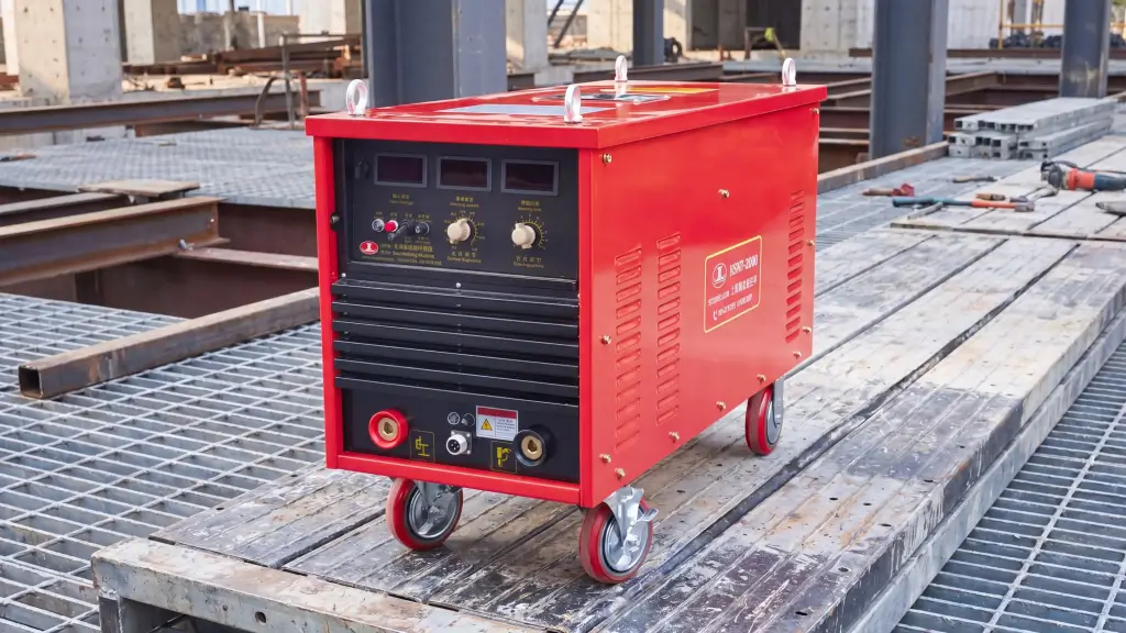
Equipment selection follows the workpiece and stud range. Compare Capacitor Discharge and Drawn Arc machines by supported diameters, input power, duty cycle and available gun setup, not price or weight alone.
CD Equipment for Small-Stud Work
A portable CD unit may fit a sheet-metal shop with small studs and limited floor space. Confirm the required supply, recharge time and rated stud range for the exact model.
- Portability: Check machine weight, input supply and cable length.
- Input power: Confirm the rating of the specific model.
- Price: Compare total equipment, guns and consumables for the job.
Size Drawn Arc Equipment for the Job
Drawn arc systems need a power source sized for the stud and duty cycle. Some are large stationary units; inverter models can be portable. Check output ratings and site power before buying.
- Duty cycle: Match the unit to planned production volume.
- Power: Site electrical requirements vary by model.
- Stud capacity: Verify the rated diameter and material.
| Equipment factor | CD welder | Drawn arc welder |
|---|---|---|
| Machine size | Often compact | Varies, including portable inverters |
| Power delivery | Capacitor bank | Sustained arc power source |
| Input supply | Check the exact model | Check the exact model |
Setup and Operator Checks

CD setup is often straightforward for repeated small studs, but it still needs correct energy, gun pressure, grounding and a clean surface. Drawn arc adds lift, weld time and plunge settings that must match the stud and ferrule.
Contact and Gap CD Setup
In contact CD welding, the tip starts against the workpiece. Keep the gun square, establish a sound return path and make test welds whenever the material or coating changes.
- Contact mode: The stud tip starts against the workpiece.
- Gap mode: The stud starts away from the workpiece; follow the gun instructions.
- Automation: Include feeding and positioning in the process design.
Drawn Arc Gun Settings
For drawn arc, set lift, time, current and plunge to the equipment and stud instructions. An off-center gun or wrong ferrule can leave an uneven fillet; verify settings with sample welds and inspection.
- Lift: Set to the manufacturer’s recommendation.
- Plunge: Set for the specified stud and ferrule.
- Gun position: Hold it square to the base metal.
| Setup factor | CD welding | Drawn arc welding |
|---|---|---|
| Operator checks | Energy, pressure, ground and position | Current, time, lift, plunge and position |
| Gun adjustments | Contact or gap mode as specified | Lift and plunge settings |
| Validation | Trial weld and inspect | Trial weld and inspect |
Choosing the Process for Your Application

Choose CD for smaller studs on thin or appearance-sensitive panels when the specified load can be verified. Choose drawn arc for larger studs and structural connections where the design and welding specification call for it. If your work falls between those cases, also evaluate short-cycle stud welding.
Conclusion
Send us your stud diameter, material grade, plate thickness, finish requirement and expected load. We can help match equipment and consumables to a trial weld; contact us today with those details.
Frequently Asked Questions
Can drawn arc weld thin sheet metal?
A conventional long-cycle drawn arc setup can distort or burn through thin sheet. Short-cycle processes and smaller studs may cover some intermediate applications. Check the approved equipment range and test the actual sheet.
Which process should I use for aluminum studs?
CD is common for small studs on thin aluminum. Drawn arc aluminum studs also exist for suitable applications, often with specified shielding. Base the choice on alloy, thickness, stud design and a qualified procedure.
How should I check stud weld quality?
Inspect the weld appearance and use the bend, torque or tensile test required by the job specification. A continuous fillet can be useful evidence for a drawn arc weld, but appearance alone does not prove its load capacity.
Can a portable CD machine weld M8 studs?
Some portable CD machines support M8 studs, depending on the model and material. Confirm the manufacturer’s rated range and test the intended stud on your base metal.
How can I reduce reverse-side marking?
Choose a process and settings that limit heat input, then make sample welds on the actual gauge and finish. CD often helps, but no process can promise an unmarked reverse side for every panel.