A shear stud is a type of shear connector. In composite steel-and-concrete construction, the terms are often used for the same headed stud because headed studs are a common way to transfer force across the steel–concrete interface. “Shear connector” is the wider term; it can also describe other engineered connection details.
That distinction matters when a drawing becomes a purchase order. The design may call for a connector function, but the welding crew needs a specific stud size, material, weld-end design and installation procedure. See our headed shear stud range for the physical product, then use the project drawing to select the correct variant.
How is a shear stud different from a shear connector?
A shear connector is any approved detail that transfers longitudinal shear between a steel member and a concrete slab. A headed shear stud is one such detail. Its shank is welded to the steel; the head is embedded in concrete and helps provide anchorage. Other connector forms may be used where the design rules and project approval allow them.
When reviewing a bill of materials, do not stop at “shear connector.” Specify the actual item. Our shear stud overview explains the headed form, while the comparison with regular weld studs shows why not every weld stud is a structural shear connector.
| Term | What it identifies | What a buyer still needs |
|---|---|---|
| Shear connector | The connection function or approved detail | Type, design reference and installation method |
| Headed shear stud | A specific welded connector form | Diameter, length, head, material and weld end |
Why are headed studs often specified?
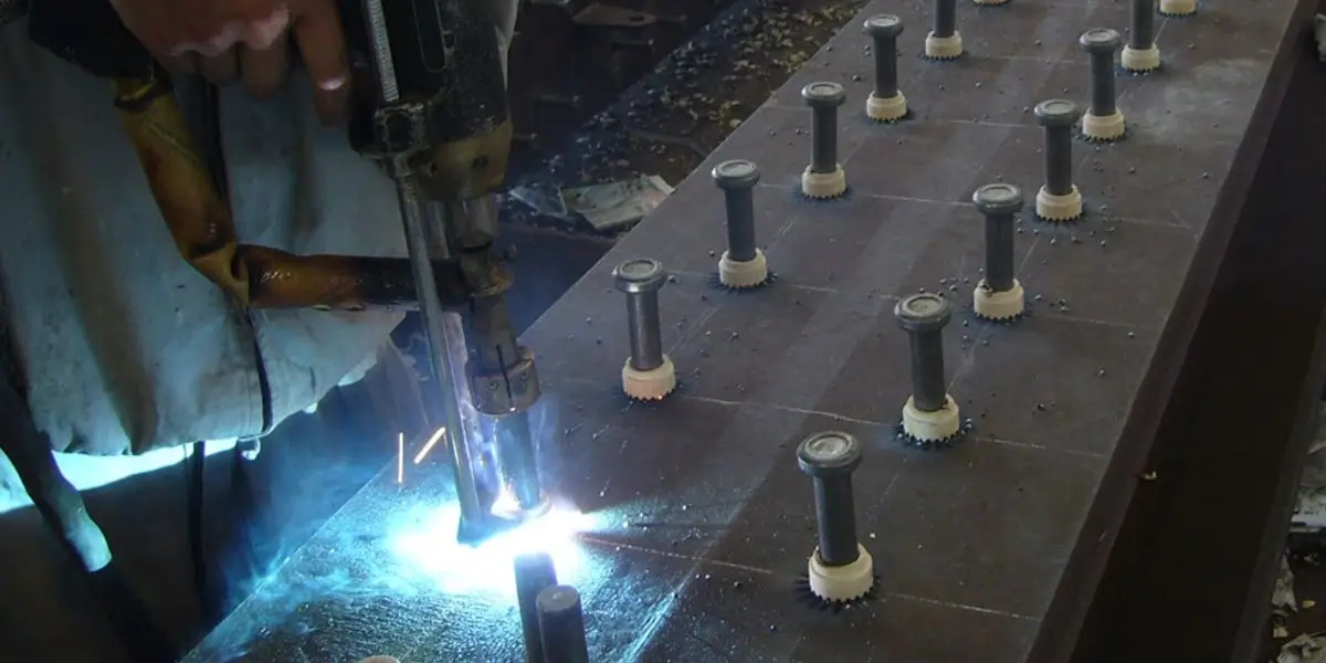
Headed studs fit established composite-beam design and installation methods. The head provides anchorage in the concrete, while the welded shank transfers force to the steel beam. Studs can be installed quickly with a suitable stud welding gun, but speed depends on access, deck profile, operator setup and inspection.
The head does not make every stud interchangeable. Its dimensions and embedment are part of the structural detail. A stud that is too short after welding, positioned poorly in a deck rib or paired with the wrong ferrule may fail to meet the intended design even if it looks similar on the shelf.
| Headed-stud feature | Design or site implication |
|---|---|
| Forged head | Provides anchorage within the concrete |
| Welded shank | Requires an approved weld to the steel member |
| Stud height | Must suit slab and deck geometry after welding |
How does welding affect connector performance?
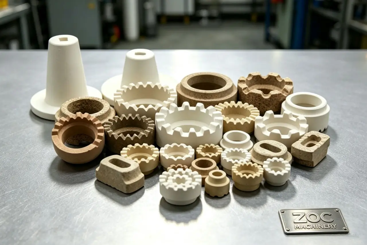
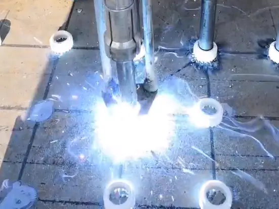
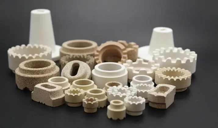
In a ferrule-shielded drawn arc cycle, the gun lifts the stud, an arc melts the stud end and base metal, and the stud plunges into the molten pool. The ferrule helps contain the metal and form the weld collar. The drawn arc stud welding process describes the sequence; the ceramic ferrule range shows why the ring must match the stud.
A full-looking collar is useful for visual inspection, but it does not prove complete fusion or a particular strength. Current, time, lift, plunge, base-metal condition and return-lead layout all affect the weld. Use the approved procedure and required tests before treating the connector as accepted.

| Cycle stage | What to control |
|---|---|
| Stud positioning | Contact surface, angle and ferrule fit |
| Arc | Current, time and lift in the approved procedure |
| Plunge and cooling | Gun movement and collar formation |
Which standards and documents matter?
ISO 13918 covers requirements and dimensions for studs and ceramic ferrules, including the SD shear-connector type. ISO 14555 addresses arc stud welding procedures, qualification and production testing. Structural design and connector resistance are governed by the project’s applicable design code and drawings. The documents serve different purposes.
Ask for the specified stud grade, dimensions and material documentation. A material test report supports traceability of the supplied stud; it is not a certificate that the site welds pass. Keep the welding procedure and inspection records with the project documentation.
| Document | Question it answers |
|---|---|
| Stud drawing and material record | What component was supplied? |
| Approved weld procedure | How must it be installed? |
| Design drawing and code | How many connectors and where? |
| Inspection record | Were the installed welds accepted? |
Can another connector replace a headed stud?
Only after the project engineer checks and approves the substitution. A channel, angle or other detail can have a different resistance, stiffness, slip behavior and installation method. Those differences affect the design calculation and detailing. A procurement substitution is not a simple like-for-like change.
If the specified stud is unavailable, send the proposed alternative with its drawings and test data for design review. Do not choose a replacement based only on a similar nominal shear capacity or a lower unit price.
| Proposed change | Review before approval |
|---|---|
| Headed stud to another connector type | Design resistance, slip, detailing and installation |
| Different stud diameter or height | Capacity, embedment, deck and reinforcement clearance |
| Different material | Weldability and service environment |
What does the connector do in a composite beam?
The steel beam and concrete slab bend differently unless force can pass between them. Shear connectors transfer force along that interface and limit relative slip, allowing the designer to use composite action. The gain in stiffness or resistance depends on the whole beam and slab design; there is no universal percentage increase from adding studs.
In a profiled deck, rib orientation and geometry affect the stud location and design resistance. The head and shank must have the specified height and concrete cover after welding. These are design details, not decisions to make by eye on the job site.

| Part | Role in the connection |
|---|---|
| Steel beam | Carries part of the composite bending demand |
| Concrete slab | Works with the beam when force is transferred |
| Shear connector | Transfers interface force and limits slip |
What can cause a connector weld to fail inspection?
Poor surface preparation, a damaged or damp ferrule, incorrect setup or a problem in the current path can leave an irregular or weak weld. A one-sided collar may point to gun alignment or arc behavior; an incomplete collar can also result from metal escaping through a damaged ring. Check the actual cause before turning up current.
If a test fails, stop using the setup and follow the project’s repair and retest procedure. Our stud welding troubleshooting guide lists other faults that can look similar. No single setting change will fix every failed connector.
| Observed problem | Check first |
|---|---|
| One-sided collar | Gun angle, ferrule seating and return path |
| Weak test result | Procedure, surface, stud and equipment |
| Metal leakage | Ferrule damage and workpiece geometry |
Who determines the number and layout of studs?
The structural designer calculates the required shear connection and lays out the studs. The answer depends on loads, beam and slab geometry, concrete properties, deck profile, stud dimensions and the governing design rules. Dividing a total force by a single catalog capacity is not enough because location and reduction factors can matter.
Installation teams should check the drawing for spacing, edge distances, deck ribs and required stud height after welding. If the deck or beam differs from the drawing, return the issue to the designer before changing the pattern.
| Design input | Why it matters |
|---|---|
| Interface shear | Sets required force transfer |
| Deck geometry | Can affect placement and connector resistance |
| Stud size and height | Affect capacity and embedment |
| Spacing and cover | Must fit the structural detail |
How should installed studs be checked?
Visual examination, trial welds and mechanical tests are specified by the applicable welding procedure and project requirements. Check the exposed collar and obvious damage after removing the ferrule. A bend test may be required, but its angle, frequency and acceptance criteria are not the same on every job.
Keep the results tied to the gun, settings, operator, stud batch and work area so a change can be traced. Our stud welding quality guide explains why visual appearance and mechanical testing answer different questions.
| Check | Purpose |
|---|---|
| Visual examination | Find visible collar, crack or alignment issues |
| Procedure test weld | Verify the setup before production |
| Specified mechanical test | Assess weld performance under the job criterion |
What should a supplier and site team confirm?
Order against the drawing: stud diameter and length, head size, material, weld-end design, quantity, documentation and matching ferrules. Confirm that the welding machines and the gun are suitable for the stud and site power supply. A single supplier can simplify coordination, but it does not remove the need for a qualified weld procedure.
ZOCMachinery can review a project schedule or stud drawing and identify available products. Ask for the actual dimensional and material records for the quoted batch, as well as the consumable and equipment configuration. Do not infer a percentage saving, stock level or certification from general marketing copy.
| Before ordering | Confirm |
|---|---|
| Stud specification | Size, material, weld end and applicable standard |
| Matching consumables | Ferrule type and quantity |
| Installation | Equipment, procedure and inspection plan |
| Supply | Batch traceability and agreed delivery terms |
What is the useful distinction?
Use “shear connector” for the structural function and “headed shear stud” when you mean the particular welded part. On drawings and purchase orders, name the connector type and give its dimensions and material. On site, match the installation and tests to that specified part. The familiar terms can be used casually in conversation; the project record should be precise.
FAQ
Is every shear connector a shear stud?
No. A headed shear stud is one form of shear connector. Other approved details exist, but they need their own design and installation requirements.
Can a shear stud be welded over paint?
Do not assume so. Prepare the weld location as the approved procedure requires; paint and other coatings can interfere with contact and welding. If the steel has a specified coating system, coordinate removal and repair with the project requirements.
How many studs can a gun install per day?
There is no reliable universal figure. Access, layout, deck work, ferrule handling, testing and repositioning often take more time than the weld cycle itself. Estimate production from a site trial.
Are ferrules included with the studs?
That is a purchase-order question. Ask for the specified matching ferrules and confirm the quantities. Do not assume they are in every box.
What if a connector fails a required test?
Stop and follow the project’s nonconformance, repair and retest procedure. Investigate the stud, surface, ferrule, equipment and settings before production resumes.