The arc stud welding process joins a metal stud to a workpiece with an electric arc. In drawn-arc welding, the gun lifts the stud, the arc melts both joining surfaces, and the gun plunges the stud into the molten metal. The result depends on more than the trigger cycle: stud and base-metal compatibility, surface condition, equipment setup, and inspection all matter. This guide explains the sequence and the decisions behind a reliable weld.
How the arc stud welding process works
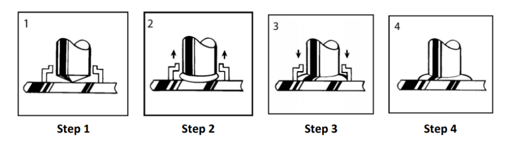
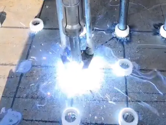
The power source and gun run a controlled cycle after the operator positions the stud. The operator still has to place the gun squarely, keep the work area ready, and use a qualified setup. Drawn arc is one member of the stud-welding family; the shorter-cycle and capacitor-discharge methods have different equipment and applications.
The sequence from contact to solidification
- Position: Fit the correct stud and shielding arrangement, then seat the gun on the workpiece.
- Lift and arc: The gun lifts the stud and the power source establishes an arc, heating the stud tip and base metal.
- Plunge: The gun drives the stud into the molten pool at the end of the programmed arc period.
- Solidify: Hold the gun steady until the weld sets; remove the ferrule, where used, after cooling.
The exact current, time, lift, and plunge settings come from the machine and stud supplier and are confirmed by procedure trials. A fast cycle does not, by itself, prove a sound joint.
| Stage | What happens | What to check |
|---|---|---|
| Position | Stud and gun are seated on the marked weld location | Stud, ferrule or gas setup, gun angle |
| Arc | Stud lifts and the two joining surfaces heat | Stable arc and appropriate settings |
| Plunge | Stud enters the molten pool | Gun movement and alignment |
| Solidification | Weld metal sets under the gun | Do not disturb the stud too early |
Prepare the base metal and work area
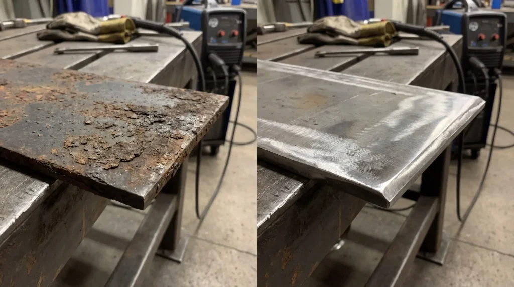
Poor contact and contamination can disrupt arc initiation and fusion. Inspect the actual weld location for oil, moisture, rust, scale, paint, primer, or thick coating. Prepare it as the approved procedure requires; do not assume every coated or galvanized surface needs the same treatment. Attach the return lead to a clean, secure point specified for the job.
A practical pre-weld check
- Confirm the stud and base-metal grades, thickness, and specified weld location.
- Remove contamination over the area the weld and shielding will cover, using a method suitable for the coating and site.
- Check that the work is dry and that the work clamp, cables, gun, and ferrule holder are sound.
- Make trial welds when the material, coating, stud size, cable arrangement, or setup changes.
For a broader preparation checklist, see our stud welding process guide. The final acceptance criteria should still come from the project welding procedure.
| Surface condition | Possible effect | Practical response |
|---|---|---|
| Oil or grease | Arc instability or pores | Clean with an approved degreasing method |
| Heavy rust or scale | Inconsistent contact and fusion | Remove to the required surface condition |
| Paint or coating | Can interfere with welding and create fumes | Follow the qualified coating-removal procedure |
| Clean, dry metal | More consistent starting condition | Keep it clean until welding |
Choose compatible equipment
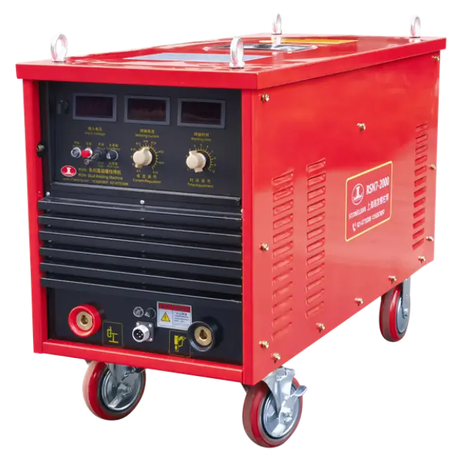
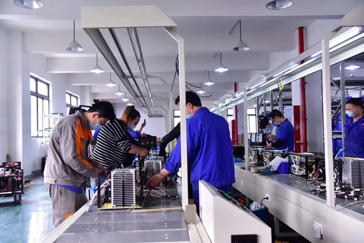
A drawn-arc setup includes a power source, welding gun, return cable, stud holder, and the specified ferrule or shielding-gas system. Start with the stud diameter and material, required duty cycle, available site power, cable length, and the manufacturer’s approved operating range. Review These machines as examples of equipment options, then check the model against the actual job.
Inverter or transformer power source?
Both designs are used in the field. An inverter may suit a crew that moves equipment frequently or needs programmable controls. A transformer-based unit may suit a fixed station or an existing fleet. Weight, input requirements, output range, service access, and duty cycle vary by model, so compare the specifications of the machines under consideration rather than treating one design as universally better.
| Selection point | Question to ask | Why it matters |
|---|---|---|
| Output range | Does the machine cover the specified stud and material? | Avoids operating outside its rated range |
| Duty cycle | Can it sustain the planned production pace? | Helps prevent interruptions |
| Site power | Is the available supply compatible? | Supports stable operation |
| Gun and cables | Are the gun, chuck, and cable length approved? | Affects setup and handling |
Set parameters for the stud and base metal
A larger stud generally needs more welding energy, but diameter alone does not determine a safe setting. Base-metal thickness, stud material, tip design, shielding, cable layout, and the power source all affect the result. Use the supplier’s starting data, then establish or confirm the welding procedure with trial welds and the required tests. Do not copy a current-and-time chart from an unrelated machine.
What to adjust during trials
- Verify the stud size and material against the machine and gun ratings.
- Set current and arc time from the supplier’s recommendations or an approved procedure.
- Check gun lift, plunge travel, foot position, and ferrule fit where those adjustments apply.
- Inspect and test trial welds before production; record the accepted setup for repeat work.
If you are choosing between processes, our short-cycle and drawn-arc comparison explains where their operating ranges differ.
| Variable | What it influences | How to establish it |
|---|---|---|
| Weld current | Heat delivered to the joint | Supplier data and procedure trials |
| Arc time | Duration of heating | Supplier data and procedure trials |
| Lift and plunge | Arc gap and stud movement | Gun instructions and trial-weld results |
| Cable and return path | Electrical conditions at the weld | Approved site setup and checks |
Recognize visible weld problems
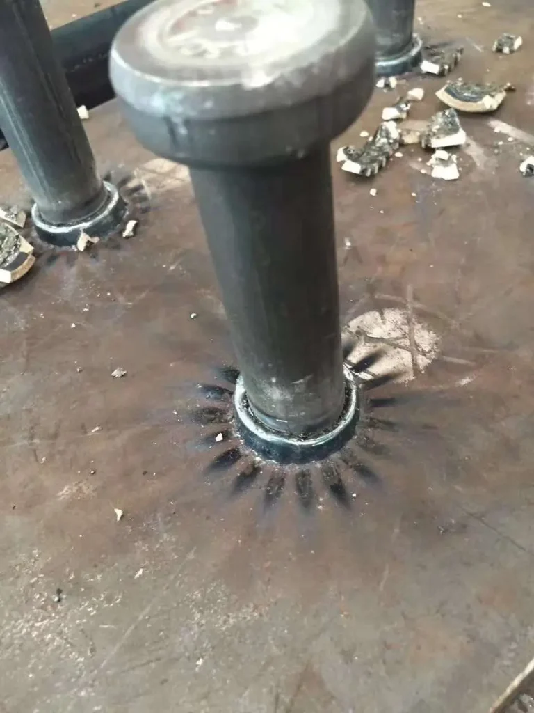
A finished weld should be examined against the procedure’s visual criteria, including the expected fillet, stud position, and any cracks, undercut, or obvious pores. A full-looking collar is useful evidence, but appearance cannot establish weld strength on its own. Color is also a poor universal pass/fail rule: material, oxidation, and cleaning affect it.
What a defect may indicate
- An incomplete or uneven fillet may point to poor gun alignment, incorrect setup, or a disturbed arc.
- Visible porosity can be associated with contamination, moisture, or shielding problems.
- Undercut or excessive spatter calls for a check of heat input and gun setup.
- A leaning stud may indicate the gun was moved or was not held square.
The next step is to stop, identify the cause, and make a new trial weld before repeating the defect across the workpiece. Our stud weld quality guide covers more inspection and troubleshooting points.
| Observation | Possible cause to investigate | Action |
|---|---|---|
| Incomplete fillet | Alignment, heat input, or shielding | Review setup and test again |
| Visible pores | Moisture, coating, or shielding | Check preparation and consumables |
| Undercut or excess spatter | Parameter or gun-setting mismatch | Compare with approved procedure |
| Stud out of position | Gun movement or access | Correct positioning and repeat trial |
Ferrules and shielding choices
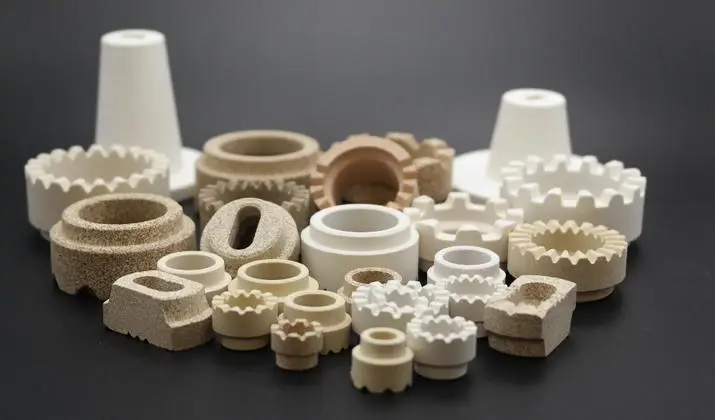
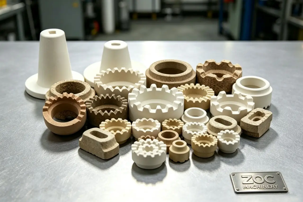
Ceramic ferrules surround the arc and help contain molten metal in many drawn-arc applications, particularly structural studs. Their shape and venting are matched to the stud. Some drawn-arc setups use shielding gas instead, and some short-cycle applications use a different protection method. Follow the procedure and consumable specification rather than assuming every stud needs a ceramic ferrule.
Check the consumable before welding
- Use the ferrule type and size specified for the stud and gun.
- Keep ferrules dry and reject damaged pieces.
- Seat the ferrule holder squarely and check that the ferrule contacts the workpiece as intended.
- Remove the ferrule after the weld has cooled enough for safe handling.
See the ceramic ferrule guide for the part each ferrule plays in weld formation.
| Ferrule role | Practical effect | Check before use |
|---|---|---|
| Arc enclosure | Limits direct exposure of the weld zone | Correct ferrule fit |
| Molten-metal containment | Helps form the weld collar | Correct size and placement |
| Gas escape | Provides a route for gases during welding | Unblocked vent design |
| Single-use consumable | Consistent geometry for each weld | Dry, intact ferrule |
Materials and combinations
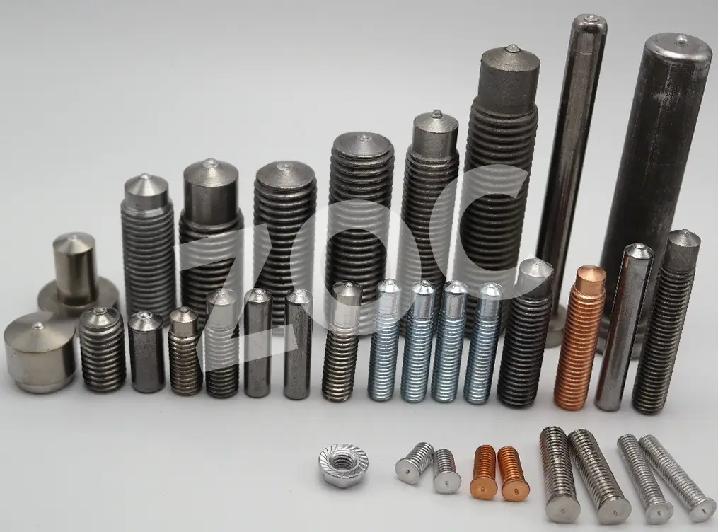
Steel, stainless steel, and aluminum stud-welding applications exist, but they do not share one setup. Choose stud and base-metal combinations on the basis of a qualified procedure and the required service conditions. Dissimilar metals need special attention to weldability and, in service, corrosion. Coatings and surface treatment also change the preparation and fume assessment.
What to confirm for each material
- The stud and base-metal grades are covered by the procedure.
- The selected machine, gun, stud tip, and shielding method are suitable.
- The base metal has enough thickness and access for the specified weld.
- The joint is inspected and tested to the project requirement.
A matching stud is as important as the power source. Its grade, dimensions, and weld end must match the procedure; a similar-looking replacement may behave differently.
| Material combination | Typical consideration | Verification |
|---|---|---|
| Carbon-steel stud to steel | Common structural use | Check grade and procedure |
| Stainless stud to steel | Weldability and service corrosion | Confirm approved combination |
| Stainless stud to stainless | Grade and shielding selection | Check procedure and finish |
| Aluminum stud to aluminum | Alloy and process suitability | Use application-specific trials |
Safety during arc stud welding
Arc light, hot metal, fumes, electricity, and nearby combustibles are the main hazards to plan for. Select eye and skin protection from the site hazard assessment and applicable rules; a single lens shade or glove type is not right for every job. Provide ventilation or fume control appropriate to the materials and workspace. Follow the equipment manual for electrical checks, and isolate hot work from combustible materials.
Before the first weld
- Assess the welding area for fumes, coatings, confined-space conditions, and fire hazards.
- Provide the required helmet or face protection, protective clothing, gloves, and footwear.
- Inspect cables, connectors, and the return path; keep electrical equipment dry and in good condition.
- Protect nearby workers from arc radiation and prevent contact with hot studs and ferrules.
| Hazard | Control to plan | Site check |
|---|---|---|
| Arc radiation | Suitable eye, face, and skin protection | Shield operator and bystanders |
| Fumes | Ventilation or extraction as assessed | Review base metal and coatings |
| Hot metal and sparks | Protective clothing and hot-work controls | Clear combustibles and mark hot parts |
| Electric shock | Sound cables and safe electrical practice | Inspect equipment and work area |
Inspect and test the welds
Visual inspection can identify obvious defects, but production welds also need the tests and sampling required by the project procedure. A bend test is commonly used in stud-welding qualification or production checks, but the method, angle, sample rate, and acceptance criteria must come from the applicable specification. ISO 14555:2025 addresses arc stud-welding procedure, qualification, and production testing; the contract may specify further requirements.
A useful quality-control sequence
- Document the approved machine, stud, ferrule or gas, and parameter setup.
- Make and evaluate trial welds at the required points in the job.
- Inspect production welds against the specified visual criteria.
- Perform and record bend or other tests at the required frequency; investigate failures before continuing.
Do not use a sound-looking fillet as a substitute for required mechanical testing, or assume a broken stud automatically proves the weld is acceptable.
| Check | Purpose | Acceptance basis |
|---|---|---|
| Visual examination | Find obvious shape, position, and surface defects | Approved visual criteria |
| Bend test | Assess weld behavior under deformation | Specified method and limits |
| Dimensional check | Confirm location and after-weld dimensions | Drawings and procedure |
| Other mechanical test | Meet a project-specific requirement | Contract or governing standard |
Where the process is used
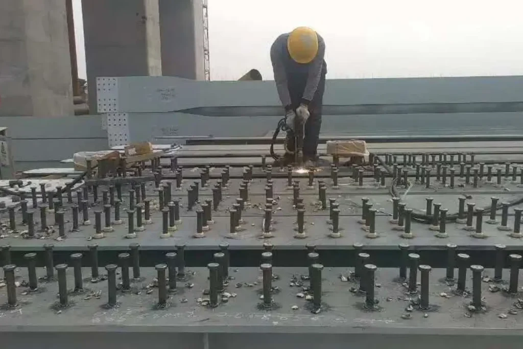
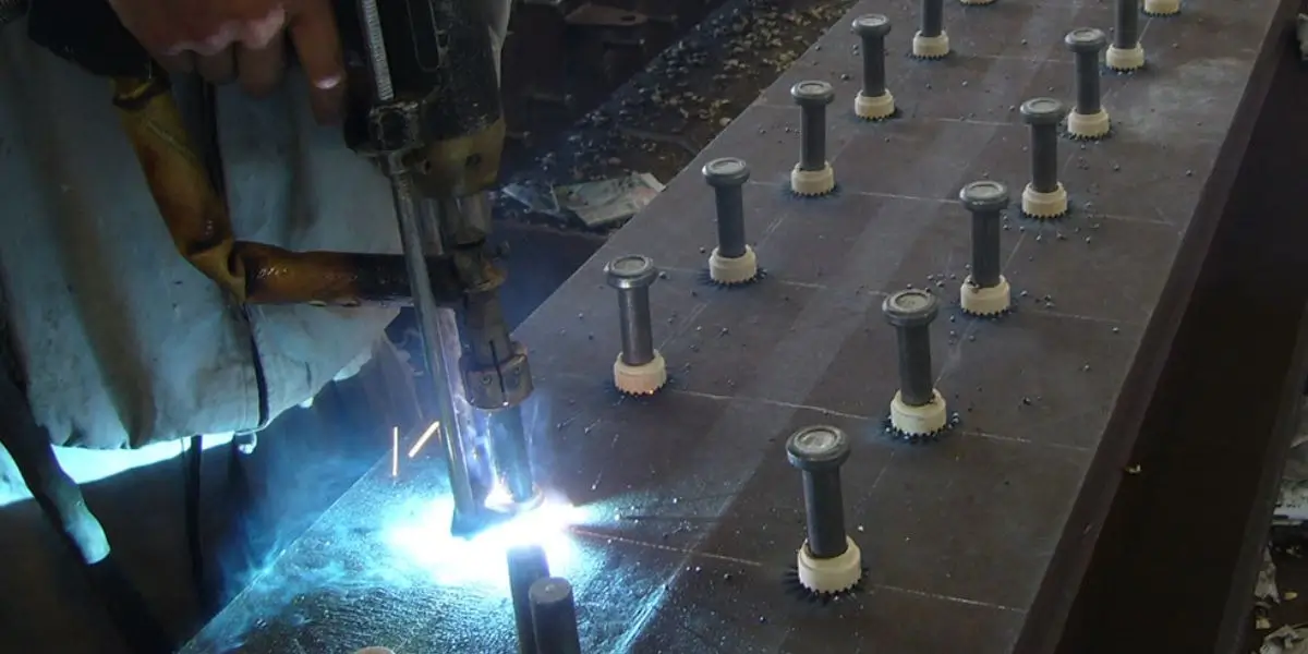
Drawn-arc stud welding is used where a welded fastener is needed on steelwork and the procedure supports the load and material. Shear connectors on beams and bridge girders are a familiar example: they transfer forces between steel and concrete in composite construction. Other uses include industrial attachments and equipment fabrication. Our shear stud applications page covers structural examples.
Match the application to the joint
A bridge shear connector, a boiler attachment, and a cable-support stud have different design and inspection requirements. Specify the stud, base material, access, production volume, and governing standard before choosing the process or equipment.
| Application | Typical stud function | Decision to confirm |
|---|---|---|
| Composite construction | Transfer shear between steel and concrete | Structural design and inspection |
| Industrial equipment | Attach components or supports | Material and service conditions |
| Energy equipment | Attach lining or insulation hardware | Heat and duty requirements |
| Marine fabrication | Attach fittings to steelwork | Corrosion and coating plan |
Frequently asked questions
Can I weld through paint or primer?
Only if the specific coating and welding procedure permit it. Many coatings interfere with the arc or create hazardous fumes; follow the approved preparation and fume-control plan.
What causes arc blow?
Magnetic fields and the current return path can deflect the arc. Check return-lead placement and cable routing under the equipment guidance, then verify the change with trial welds.
How do I know the lift setting is right?
Use the gun and power-source instructions, then confirm it through trial welds and the required inspection. Fillet appearance alone is not a precise lift measurement.
Can one machine perform capacitor-discharge and drawn-arc welding?
Only if its manufacturer explicitly rates it for both methods. The power delivery and gun setup differ. Our capacitor-discharge versus drawn-arc guide explains the process choice.
What if a ceramic ferrule is damp or damaged?
Replace it and check storage conditions. Moisture or damage can affect the weld; do not rely on a visual steam cue to decide whether a ferrule is usable.
Plan the procedure before production
The arc stud welding process can attach studs quickly, but repeatable results come from a matched stud, power source, gun, shielding method, and documented procedure. Set up on the actual material, test trial welds, and inspect production welds to the specified acceptance criteria. If you need help selecting equipment for a planned stud size and duty cycle, ZOC Machinery can review the application; contact us with the stud and base-metal details.