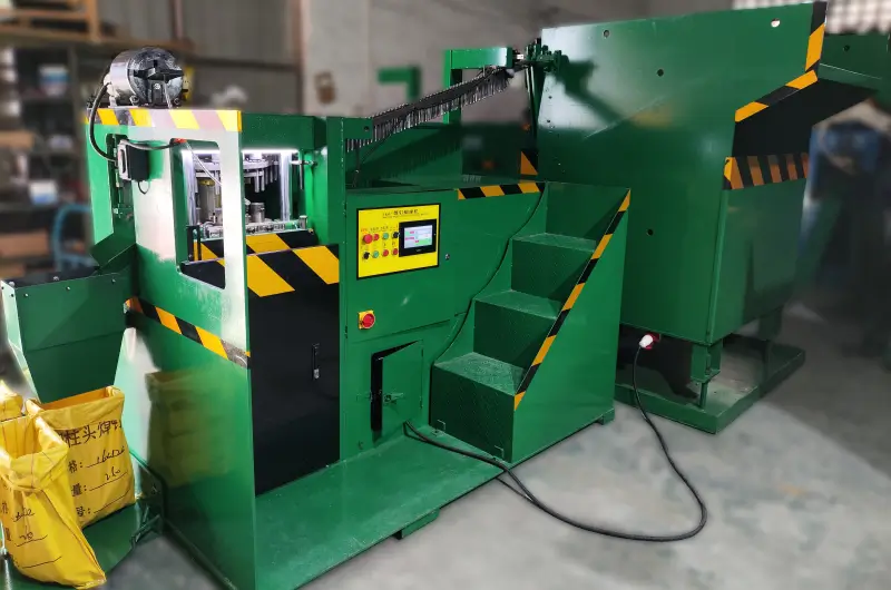
A shear stud flux fixing machine seats an aluminum ball in the stud’s weld-end cavity before the stud reaches the welding site. It is a manufacturing step, not a stud welder. The hydraulic station can reduce repeated hand placement and make ball position more consistent, but the finished stud and the field weld still need their own checks.
ZOC lists an automatic machine with feeding, hydraulic fixing, in-process detection, counting and optional packing functions. Its published capacity is up to 70 pieces per minute, depending on stud size and feeding conditions. Use that as a model rating to test against your actual parts, not as a guaranteed shift output.
Why Fix Aluminum Balls to Shear Studs?
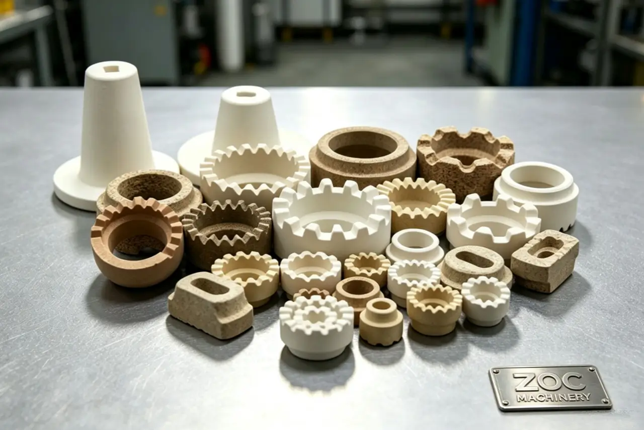
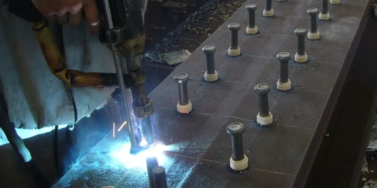
The aluminum ball is held at the weld end of compatible shear studs before drawn arc welding. Its size and seating have to match the stud tip design. This is separate from the ceramic ferrules in drawn arc welding that surround the weld pool at the workpiece. Our comparison of shear studs and other weld studs helps identify which connector and end preparation a project specifies.
| Production concern | What the fixing station can control | What still needs checking |
|---|---|---|
| Ball position | Repeatable placement with matched tooling | Ball size, stud cavity and retention |
| Handling | Automatic feed and transfer | Jams, changeovers and accepted output |
| Final weld | Supplies a prepared stud | Welding procedure, site conditions and weld inspection |
A well-seated ball helps keep the incoming studs consistent. It cannot guarantee arc stability, penetration or a passing bend test on its own; the power source, ferrule, base metal and welding procedure matter too.
How the Hydraulic Flux Fixing Machine Works
The line feeds prepared studs and aluminum balls to the fixing station. Tooling positions each stud, the hydraulic unit seats a ball in its cavity, and the finished part moves to detection and counting. The exact sequence and reject handling depend on the machine configuration.

- Feed clean studs and correctly sized aluminum balls to their tracks.
- Position the stud so its weld-end cavity aligns with the fixing die.
- Seat the ball with the configured hydraulic stroke and tooling.
- Check the output, count accepted parts and route them to the selected packing station.
| Stage | Equipment role | Operator check |
|---|---|---|
| Feeding | Presents studs and balls to the station | Orientation and supply |
| Fixing | Hydraulic stroke seats the ball | Die fit and ball retention |
| Detection | Flags a monitored abnormal condition | Rejects and false stops |
| Counting | Builds a preset batch | Count accuracy and packing flow |
The shear stud flux fixing machine product page shows a PLC-controlled hydraulic workflow. Ask for a run with your own stud and ball samples to confirm feed behavior, seating and reject handling.
Match Tooling to Stud and Ball Size
ZOC lists standard configurations for Ø10–Ø25 mm studs and lengths of 50–300 mm. These are published machine ranges, not a promise that one die handles every size. Cavity shape, ball diameter, stud length and the packing layout all affect the final tooling package.
| Input | Information to send with the drawing |
|---|---|
| Shear stud | Diameter, length, material and weld-end cavity |
| Aluminum ball | Diameter, material grade and tolerance |
| Production mix | Sizes per shift and expected changeover frequency |
| Output | Required accepted pieces per shift and packaging format |
A size change may require a different clamp, positioning tool or fixing die and a new machine setting. Have the supplier demonstrate the changeover and give you a tooling list for every stud in the order.
Measure Production Capacity and Packing
The published “up to 70 pieces per minute” figure describes a favorable machine cycle. Actual accepted output falls when feeding pauses, dies change, parts are rejected or cartons are switched. For an eight-hour plan, use a timed trial with your stud sizes rather than multiplying the maximum rate by 480 minutes.
| Measure | How to evaluate it |
|---|---|
| Machine rate | Accepted pieces during a stable sample run |
| Shift output | Accepted pieces after changeovers, jams and breaks |
| Rejects | Missing, loose, damaged or mispositioned balls |
| Packing | Batch count and station capacity for your carton or bag |
ZOC lists preset counting and up to four circulating packing stations as configuration options. Confirm the stations, counters and interfaces included in the specific quote; an automatic counter does not verify every quality feature.
Quality Checks and Standards
ISO 13918 specifies requirements for studs and ceramic ferrules, including dimensions, materials and mechanical properties. It does not certify a flux fixing machine or guarantee that a field weld will pass. Specify the stud standard, the ball and cavity dimensions, retention criteria and inspection sampling separately.
| Check | Evidence to request |
|---|---|
| Incoming parts | Stud and ball dimensions with batch identification |
| Fixed ball | Position, damage and retention results from a sample |
| Machine detection | What faults the sensors actually detect and how rejects are handled |
| Weld performance | Procedure and weld-test records for the finished stud |
A missing-ball sensor can help catch one defect; it is not a substitute for sampling ball retention or testing welds. Our stud weld quality checks and stud welding process parameters guides cover the downstream checks after the prepared stud reaches the welder.
PLC Controls and Fault Handling
The controller coordinates feeding, station movement, fixing and counting. Ask the supplier to show which settings operators may change, which faults stop the machine and how rejected parts are separated. Features such as a touchscreen, stepper indexing or multilingual menus should be confirmed on the quoted configuration.
| Control function | Acceptance test |
|---|---|
| Recipe change | Run every quoted stud and ball combination |
| Abnormal stop | Trigger a safe fault and check the displayed message |
| Counting | Compare the counter with a physical batch count |
| Restart | Confirm a jam can be cleared under the approved safe procedure |
Keep access to setup changes limited to trained staff and save the approved recipe for each stud drawing. A PLC makes settings repeatable; it cannot correct the wrong die or an out-of-tolerance ball.
Maintenance for Repeatable Fixing
Follow the delivered machine’s service manual for lubrication, hydraulic oil, filters, hoses and die wear. Service intervals and oil grade depend on its configuration and operating conditions. Record pressure, abnormal stops and rejected parts so a change in the fixing process is visible before it becomes a batch problem.
| Item | What to inspect | When to act |
|---|---|---|
| Fixing die | Wear, looseness or ball damage | When sample position or retention drifts |
| Feed track | Debris, misfeeds or orientation errors | When jams or rejects rise |
| Hydraulics | Leaks, pressure changes and oil condition | By the delivered machine manual |
| Sensors | Detection and reject behavior | During planned checks and after service |
Isolate the machine before servicing the hydraulic station or clearing a jam. Use replacement parts and oil grades approved for the delivered unit.
Guarding and Operator Safety
The fixing station has pinch points and stored hydraulic energy. Review the guarding, emergency-stop circuit, interlocks and fault-recovery sequence on the actual machine. A light curtain or particular sensor should not be assumed unless it is included in the specified configuration and acceptance test.
| Safety item | What to verify on site |
|---|---|
| Guarding | Operator cannot reach the die during a cycle |
| Emergency stop | Stops hazardous motion and requires a controlled restart |
| Jam clearing | Isolation and pressure-release steps are documented |
| Training | Operators know setup limits and fault response |
Do not use a manual or maintenance mode to bypass a safeguard. Have qualified personnel verify the electrical and hydraulic installation against the supplied drawings and local requirements.
Build a Cost-per-Accepted-Stud Case
Automation is useful when it removes a bottleneck at your production volume. Compare the installed machine and tooling cost with labor, ball waste, rejected studs, downtime and packing work in the current process. The payback period depends on that measured baseline; no fixed six-month or twelve-month return is supported by a machine brochure.
| Cost input | Use your own figure for |
|---|---|
| Capital cost | Machine, dies, feeders, packing and installation |
| Operating cost | Labor, electricity, oil, parts and service |
| Quality loss | Rejected studs, rework and sample testing |
| Throughput | Accepted studs per shift at the planned product mix |
For a purchase decision, request an acceptance run with the full product mix. Record good parts, jams, changeover time and operator involvement. Those measurements matter more than a theoretical pieces-per-hour figure.
Plan Installation Around the Quoted Configuration
ZOC lists an approximate net weight of 3,000 kg and more than one machine dimension, with layout changing by model and packing setup. Ask for a general-arrangement drawing, foundation load, service clearances and the electrical and hydraulic requirements before planning the floor space.
| Installation input | Document to request |
|---|---|
| Floor and layout | Footprint, weight, fixing points and maintenance clearance |
| Utilities | Rated input supply, cable schedule and hydraulic information |
| Material flow | Stud and ball loading plus rejected and finished-part routes |
| Commissioning | Trial-run plan, safety tests and operator training |
A qualified electrician should connect and test the supply to the delivered machine documentation. The exact input voltage, wiring and phase checks must appear in the order and commissioning plan.
Request a Demonstration with Your Studs
Send the shear-stud drawing, ball specification, monthly volume and packaging requirement. Ask for a video or witnessed test showing feed, fixing, rejection, counting and changeover on your samples. See the shear stud flux fixing machine product overview for the standard configuration.
At ZOC Machinery, we can match a machine and tooling package to the parts you plan to make. Please contact us with your drawings and target accepted output so the quotation can be tied to a testable setup.
Frequently Asked Questions
Can one machine handle different stud lengths?
The published standard range is 50–300 mm, subject to the model and tooling. Send each drawing and ask for a changeover demonstration; do not assume every length uses the same feed track or die.
How can I reduce material jams?
Control incoming stud straightness, ball size and feed-track cleanliness. Then review the machine’s fault log and reject samples to see where the jam starts. A detection system stops the line only for faults it is designed to recognize.
How do I check ball retention?
Agree on a measurable retention and position criterion with the stud buyer, then sample finished studs from the run. Confirm that the machine’s detection method covers the defects you need to reject.
Can it run continuously?
Use the supplier’s duty and maintenance data for the quoted configuration. A trial shift with your product mix is the best way to estimate sustained accepted output and planned stoppages.
Which hydraulic oil should I use?
Use the grade stated in the delivered machine manual for the site temperature and hydraulic unit. Do not substitute an oil solely because a general article names it.