Stud welding for steel structure construction joins headed shear connectors or other specified studs to structural steel. On a composite floor, the connectors transfer shear between the beam and the concrete slab so the two can act together. Drawn arc stud welding makes the joint in a controlled lift, arc and plunge cycle. The result depends on the stud, base metal, equipment setup and inspection required by the project—not on a promised weld time or strength figure.
Stud Welding for Steel Structure Construction: What It Does
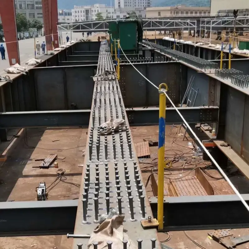
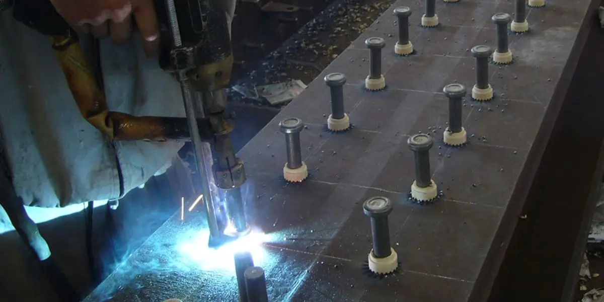
For composite beams, headed shear studs are welded to the steel flange in the positions shown on the structural drawings. The designer specifies their size, spacing and strength. A sound weld must meet the applicable procedure and acceptance criteria; it is not automatically stronger than the stud.
What Makes the Connection Work
Stud welding avoids drilling the beam for each connector and can be efficient on a large deck. It still needs access, clean contact, suitable ferrules, the right gun setup and checks during production.
- The weld must meet the specified size and acceptance criteria.
- No through-hole is needed for a welded stud connection.
- Confirm stud and base-metal compatibility for the project.
- Inspect the completed joint; appearance alone does not prove strength.
| Characteristic | Manual attachment | Stud welding |
|---|---|---|
| Joint | Depends on specified detail | Stud fused to base metal |
| Installation | May require multiple steps | Controlled weld cycle |
| Verification | Inspect to procedure | Inspect to stud-weld procedure |
Why Contractors Use Stud Welding
The installation rate can be high when studs are laid out, the surface is prepared and the crew can move safely between weld locations. Plan output using a trial area on your own deck. Handling ferrules, moving cables and inspecting welds all add time.
Plan Labour Around the Whole Job
A consistent welding cycle can reduce variation compared with hand-making each attachment, but it does not replace trained operators. Labour and cost comparisons should include preparation, consumables, testing and any rework.
- Measure output on a representative work area.
- Allow time for setup, layout and inspection.
- Train operators on the approved procedure.
- Include access equipment and cable moves in the schedule.
| Planning factor | Manual method | Stud welding |
|---|---|---|
| Cycle | Measure on site | Measure accepted studs per shift |
| Labour | Depends on joint detail | Includes setup and inspection |
| Cost | Include preparation and access | Include consumables and rework |
How Drawn Arc Stud Welding Works

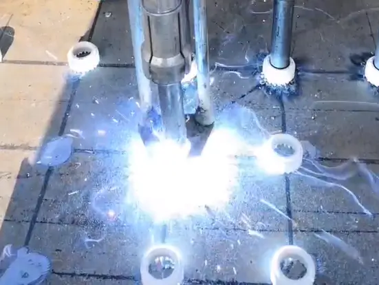
Structural shear studs commonly use drawn arc stud welding. The gun lifts the stud from the steel, an arc melts the stud end and base metal, and the gun plunges the stud into the pool. Current, time, lift and plunge are set for the stud and job procedure.
Lift, Arc and Plunge
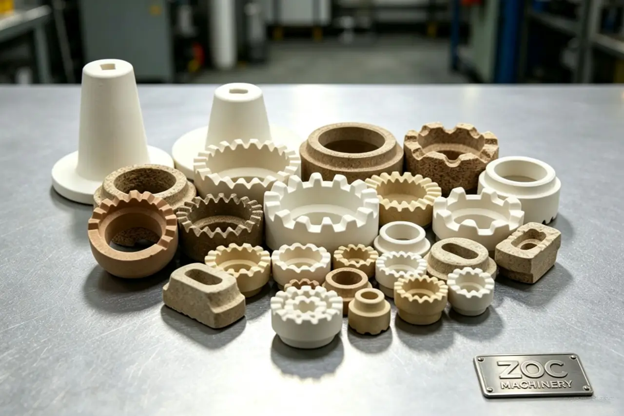
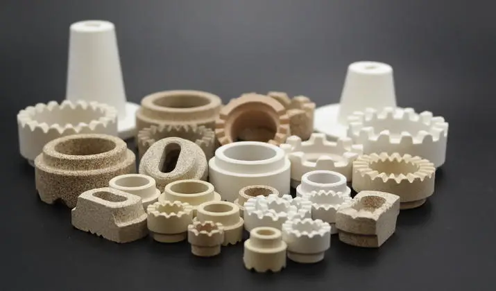
When the gun lifts the stud, the arc forms across the gap. A correctly matched ceramic ferrule surrounds the weld area and helps contain the molten metal. After the plunge, allow the joint to solidify before removing the ferrule and inspecting the weld.
- Set lift for the specified stud and gun.
- Use a ferrule matched to the stud and surface.
- Set weld current and time for the approved procedure.
- Keep the gun square and inspect surrounding steel.
| Sequence | What happens | What to check |
|---|---|---|
| Contact | Stud meets prepared surface | Position and ground return |
| Lift and arc | Gun lifts; arc forms weld pool | Current, time and lift |
| Plunge | Stud enters molten pool | Plunge and finished collar |
Studs and Ferrules for Steel Structures
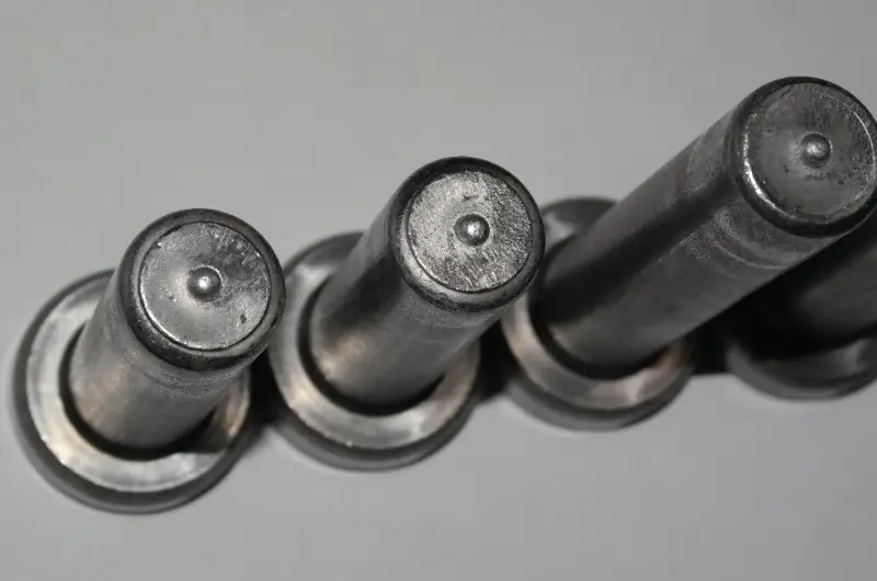
Headed shear connectors are the usual choice where a concrete slab and steel beam are designed to work as a composite member. Our guide to shear studs explains their shape and function. Other stud types are used for equipment attachments, anchors or precast work when the design calls for them.
What the Flux Tip Does
Some headed studs use an aluminum flux tip to help start the weld and deoxidize the pool. Use the stud and ferrule combination specified for the process; not every stud design uses the same tip. See how ceramic ferrules work for their role in containing the arc and shaping the weld.
- Headed studs transfer shear in composite beams.
- Threaded studs can carry specified attachments.
- Other anchor types require their own design and procedure.
- Check any flux tip required by the stud design.
| Stud type | Typical application | Design check |
|---|---|---|
| Headed shear stud | Composite steel–concrete member | Shear capacity and layout |
| Threaded stud | Specified equipment attachment | Tension or service load |
| Other anchor | Application-specific detail | Approved stud and procedure |
Inspecting Structural Stud Welds
Inspect welds to the project specification, starting with stud position and a consistent weld collar where the procedure calls for one. Visual inspection alone cannot prove load capacity. The governing code, such as ISO 14555:2025 where specified, determines procedure qualification and production testing. Agree on these stud weld quality checks before production.
What a Bend Test Shows
A bend test checks whether a representative stud and weld tolerate the prescribed deformation without unacceptable cracking or separation. Use the angle, sampling rate and acceptance rules in the governing standard and project documents; a single bend does not certify every weld.
- Inspect the weld collar to the applicable criteria.
- Do not use a sound-only test as sole acceptance evidence.
- Look for asymmetry, porosity and incomplete fusion indicators.
- Test representative welds as the specification requires.
| Inspection | Check against | Possible concern |
|---|---|---|
| Visual | Specified collar and position | Incomplete or uneven weld |
| Bend test | Required angle and sample plan | Cracking or separation |
| Other tests | Project specification | Unverified load capacity |
Where Steel-Structure Stud Welding Is Used
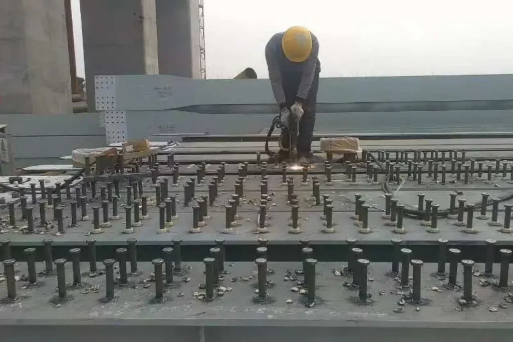
The best-known application is a composite floor: studs connect the steel beam to the concrete slab. Similar shear connectors are used in bridge decks and other composite members where the structural design specifies them. Stud welding also attaches non-composite components, but those joints have different loads and acceptance criteria.
Composite Floors and Bridge Girders
On a bridge girder, headed studs may be welded to the top flange before the deck concrete is placed. Their layout and capacity come from the bridge design. If welding through profiled steel deck, the deck geometry and approved procedure affect placement and weld quality.
- Bridge girders use shear connectors where the design calls for them.
- Composite floors use studs between the beam and slab.
- Industrial steelwork may need different stud attachments.
- Shipbuilding applications have their own specifications.
| Application | Connection role | Design basis |
|---|---|---|
| Composite floor | Beam–slab shear transfer | Connector layout and deck |
| Bridge girder | Composite deck connection | Bridge design and fatigue |
| Industrial steelwork | Specified equipment attachment | Load and access |
Equipment for Structural Stud Welding
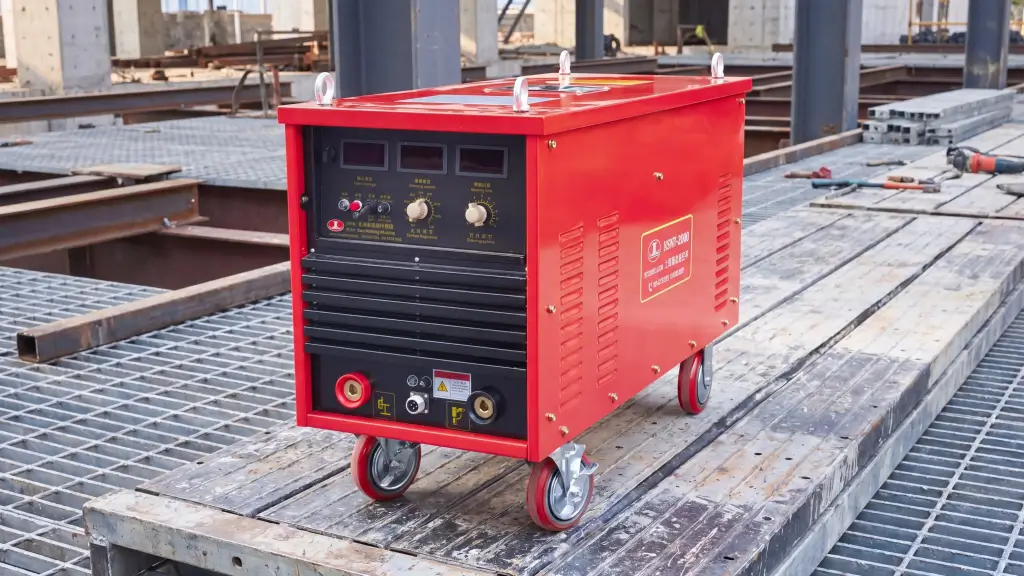
Choose the power source by the specified stud diameter, process, duty cycle, cable length and site supply. An inverter or thyristor machine may be suitable, depending on the model. Do not assume a current rating alone proves it can make your project weld.
Compare Power Sources by the Job
Inverter models can offer useful control and a smaller package, while other power sources may suit long duty cycles or existing site systems. Compare the rated output, input supply, protection, cable losses and service arrangements for the actual unit.
- Compare power consumption using model data.
- Check displayed settings against recorded weld parameters.
- Confirm cooling and duty-cycle ratings.
- Verify the site supply stays within the machine rating.
| Power source | Check first | Practical note |
|---|---|---|
| Inverter | Stud range and duty cycle | May offer compact control |
| Thyristor | Stud range and site supply | Compare model ratings |
| Other process | Approved stud and base metal | Do not substitute without qualification |
Preventing Common Weld Defects
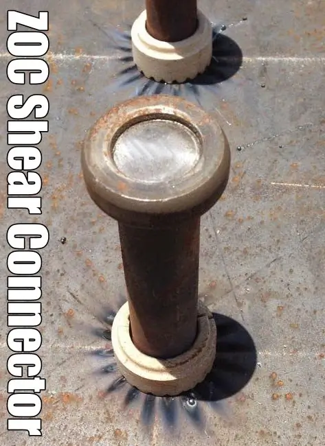
Most avoidable defects start with setup: poor return contact, unsuitable or damp ferrules, contamination, a loose chuck, wrong lift or incorrect settings. Clean the weld area as the procedure requires, keep ferrules dry and check sample welds after changes to material, leads or equipment. Our common stud welding problems guide covers typical symptoms and checks.
Checking for Arc Blow
Arc blow deflects the arc and can leave an uneven collar. Check the return-cable location, magnetic conditions and gun position. Moving or adding a return connection may help, but confirm the remedy with trial welds rather than assuming one clamp arrangement always works.
- Store and use ferrules in the required condition.
- Position return connections to reduce arc deflection.
- Check lift and plunge after changing the gun or stud.
- Investigate damp ferrules when porosity appears.
| Defect | Check for | First action |
|---|---|---|
| Porosity | Moisture and contamination | Check ferrule and surface |
| Uneven weld | Arc blow or gun position | Review return path and setup |
| Shallow fusion | Settings or poor contact | Test against approved procedure |
Measuring Installation Efficiency
Stud welding can make repeated connections quickly because the gun controls the weld sequence and the operator does not need to drill a hole for each stud. The useful measure is accepted studs per shift, including inspection and rework—not a best-case pulse time.
Count Accepted Welds, Not Just Cycle Time
Layout, safe access, cable routing and consumable handling often limit output on a deck. A second gun or an automatic flux-tip preparation step only helps if the power source, crew and workflow can support it.
- One-sided installation can simplify access.
- No through-hole is needed in the beam for a welded stud.
- Allow for ferrule removal and inspection after welding.
- Measure accepted studs per shift on your site.
| Method | Access | Timing measure |
|---|---|---|
| Stud welding | Usually one side | Accepted studs per shift |
| Through-bolting | Per connection detail | Installed and inspected joints |
| Manual fillet | Per joint detail | Accepted joints per shift |
Choosing a Stud Welding Machine for Steel Structures
Start equipment selection with the largest and smallest specified studs, base metal, welding method and site power. Then check duty cycle, gun reach, cable length, weather protection and spare parts. Our steel-structure machine guide covers these buyer checks in more detail.
When a Dual-Gun System Helps
On a large floor, a dual-gun machine may let two operators share a power source. Confirm whether the model can run both guns at the required settings and duty cycle. Two outputs do not automatically double accepted welds per hour.
- Match output range to specified stud sizes.
- Check protection rating against site conditions.
- Confirm spare-part availability and service route.
- Save approved settings where the machine supports it.
| Equipment feature | Potential use | Verify |
|---|---|---|
| Dual gun | Two-operator work area | Simultaneous output and duty cycle |
| Single inverter | General site work | Stud range and site supply |
| Specialized unit | Application-specific work | Approved process and service |
Frequently Asked Questions
Can shear studs be welded through metal decking?
Sometimes. The deck profile, thickness, coating, stud position, ferrule and welding procedure all matter. Use the through-deck method only where the design and project specification allow it, and qualify the setup on representative material.
How can I reduce porosity in structural stud welds?
Keep ferrules dry, prepare the steel surface as specified, check the stud and flux tip, and use approved settings. If porosity appears, inspect the joint and make sample welds before changing production parameters.
How do I know the machine settings are right?
Start with the manufacturer’s settings for the stud and process, then make trial welds on the actual material. Record current, time, lift and plunge where applicable and apply the project’s visual and mechanical acceptance tests.
Can I use an ordinary arc welder for structural shear studs?
Use a stud-welding power source and gun qualified for the specified stud and process. A general-purpose arc welder should not be treated as an equivalent without an approved procedure and demonstrated weld performance.
What stud diameter should I use on a 15 mm plate?
Plate thickness alone does not set stud diameter. The structural designer selects it from the required connector capacity, spacing, base metal and relevant code. Confirm that the machine, ferrule and welding procedure cover the chosen size.
Plan the Weld Procedure Before Buying
For a steel-structure project, send us the stud schedule, steel and deck details, site power and required production rate. We can help match a machine, gun and consumables to a trial weld. Contact us with those details for a quotation.